Facts Worth Knowing about AC Drives – Saving Energy with AC Drives Sections 5.1 – 5.4.2
September 14, 2020
5.1 Potential
Electric motors account about 50% of global electrical energy consumption *). In Industrial applications the ratio is even higher. Depending on the region and the industrial area, 65-75% of electrical energy in industry is used for electric motors. Therefore, electrical drive technology holds a great deal of potential for reducing the worldwide energy consumption.
AC drives enable the development and improvement of more energy-efficient motor technologies. Even more beneficial is applying the main reason why AC drives were developed: adjustable speed control. Speed control helps to optimize processes and operate motors at optimal speed and torque.
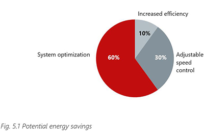
When total potential savings that could be made in a system are defined as 100%, roughly 10% of that potential could be obtained by using more efficient components, such as motors. Operation with adjustable speed control offers potential energy savings of approx. 30%.
However, the greatest savings (approx. 60%) are to be made by optimizing the entire system.
If a few key points are taken into consideration, AC drives can lead to high energy savings being quickly and easily realized as the majority of applications (approx. 60-70%) are suitable for speed control. In particular, fans and pumps – which cover almost 50% of the applications – are obvious targets because of their huge saving potential.
5.2 Motor + AC Drive Efficiency
The efficiency of a system consisting of a motor operated by an AC drive can be calculated by multiplying the single efficiencies.
ηSystem=ηMotor × ηAC drive
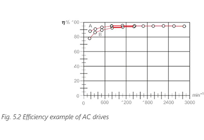
Typically, AC drive efficiency curves at two different loads are shown in Fig. 5.2 Efficiency example of AC drives (A = 100% load / B = 25% load). The efficiency of the AC drive is high throughout the control range, both at high and at low load levels.
Beside the economical aspect that high efficiencies of AC drives result in lower energy consumption, the dissipated power that has to be removed from the installation is reduced. This is important if the AC drive is integrated into a cabinet. If the losses are too high separate cooling devices are required which consume energy as well.
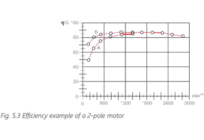
Normal and part load efficiencies of motors are compared to the AC drive as illustrated in Fig. 5.3 Efficiency example of a 2-pole motor (A = 100% load / B = 25% load).
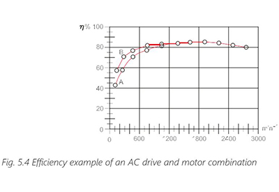
Consequently, the motor has a major influence on the system efficiency (Fig. 5.4 Efficiency example of a AC drive and motor combination (A = 100% load / B = 25% load).
Matching individual components to a particular drive system has several advantages over pre-configured systems because this allows the engineer to optimize the system to his requirements. Pre-configured systems are always optimized for general applications and can never fit all. If available, an indicator for the efficiency of components is the efficiency class.
5.3 Classification of Energy Efficient Components
AC Drive
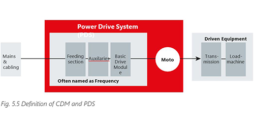
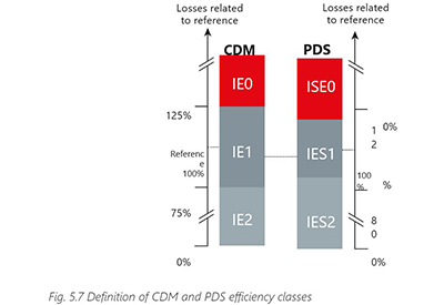
The standard IEC61800-9-2 defines efficiency classes for AC drives. As power electronics can have several configurations the classes IE0-IE2 are defined for Complete Drive Modules (CDM) consisting of rectifier, intermediate circuit and inverter (see Fig. 5.5 Definition of CDM and PDS). CDM with ability to feedback (e.g. braking energy to the mains) are addressed but not covered because they have typically higher losses, and their suitability for a particular application can be evaluated using a system level calculation and considering the particular load cycle.
The IE classes are defined in relation to a reference CDM (RCDM). By having the same scale for all power sizes, the classes are defined by relative losses. CDM with relative losses in the range of ± 25% of the RCDM is classified as IE1. CDM with higher losses are grouped in IE0 while CDM with lower losses are in class IE2 (see Fig. 5.5 Definition of CDM and PDS efficiency classes).
The rating does not reflect the CDM efficiency at lower speed / torque as it’s determined at 90% relative speed and 100% relative torque-producing current. For verification the CDM is tested with all included components at a defined test load. Fine tuning or a special test mode is not allowed.
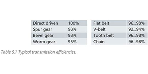
Transmission
Even though the kind of transmission can have a huge impact on the system efficiency, no efficiency classes are defined. The following table gives an indication of typical efficiencies:
Motors
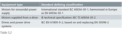
For the power range 0,12-1000 kW, efficiency classes IE1-IE4 for electric motors are defined in the standard IEC/EN 60034-30-1. Although the standard is valid for all motor types some motor constructions (e.g. brake motors) are excluded from the standard.
Several countries and regions use the IE class limits to define Minimum Efficiency Performance Standards (MEPS) to restrict the use of low efficiency motors. The efficiency class is related to the nominal operating point of the motor. Efficiencies at full speed but reduced torque must be stated on the nameplate or in the documentation. Limits are different for supply frequencies (50/60Hz) and the number of motor poles (2, 4 or 6 poles). Classes for motors operated with AC drives are defined in IEC/ EN 60034-30-2.
AC Drive + Motor Combination
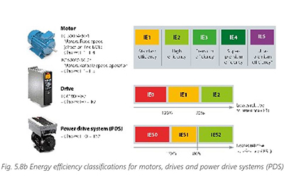
Efficiency classes for AC Drive and Motor combinations are defined in the standard IEC 61800- 9-2 via an IES rating. Similar to the CDM, the classes of the so-called Power Drive System (PDS), which is the motor + AC drive combination (see Fig. 5.8b Energy efficiency classifications for motors, drives and power drive systems (PDS), are related to a reference system (see Fig. 5.8b).
Energy efficiency classifications for motors, drives and power drive systems (PDS). PDS with 20% higher losses than the reference is in class IES0 while systems with 20% lower losses are in class IES2.
The classification is made for 100% relative speed and 100% relative torque. If the AC drive is designed for a shorter cable or it’s directly mounted on the motor where shorter cable can be used this must be stated in the documentation. In general, all kind of optimizations are possible as long they are noted in the documentation. Consequently, comparing two PDS ratings is difficult because they will most likely have different bases.
The IES class for AC drive and motor combinations illustrates the difficulty in optimizing a system and that all components must be carefully selected to optimize the application. The difference between pre-configured and non-optimized free combined systems will most often be minor, but matching different components generally allows finer adjustment to the machine, giving the machine builder a competitive advantage.
Tools for energy efficiency calculations
For helping users to deal with energy efficiency related aspects, Danfoss has developed the MyDrive ecoSmart tool. This can be used to calculate the efficiency class and part load efficiency of a Danfoss drive, either as standalone product (CDM) or in combination with a motor (PDS).
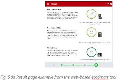
This tool makes it easy to combine a Danfoss drive with any motor, as the resulting system efficiency will be calculated by the tool, based on the motor data and drive selection. MyDrive ecoSmart is available as web application (see ecoSmart.danfoss.com) and as iOS or Android app.
Motors, drives, and power drive systems (PDS) are classified in energy efficiency classes. The standards used for classifications are different, as is the number of efficiency classes.
5.4 Load over Time
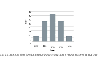
Every component in a system has some losses, so adding components to a system should be avoided if possible. This applies also to AC drives. Adding a unit to a motor which has to run all day at full load and full speed will only result in additional losses. But as soon as reducing speed and torque make sense to the application, the use of an AC drive will reduce the energy consumption. The achievable savings depend on the load profile over time, the torque characteristics and the efficiency of the motor and drive system at the given part load points.
Part load is used in two different contexts. When a motor is operated from the mains, the feeding motor frequency is fixed, and the speed only varies with load. When the motor is operated by an AC drive, part load describes torque at a certain speed where the torque characteristic is given by the application. Actually, the majority of applications are operated at part load. This is also true for mains driven motors as they are typically oversized.
5.4.1 Applications with Variable Torque
Variable torque applications often involve pumps and fans. However, a distinction has to be made in the case of pumps. Although the most popular types of centrifugal pump have a quadratic torque characteristic, eccentric, vacuum or positive displacement pumps have a constant torque characteristic.
The energy saving potential of centrifugal pumps and fans is very high as these machines follow the affinity laws.
Q1 n1
Q2 ~ n2 Flow is proportional to speed
H1 n1 2
H2 ~( n2 ) Pressure or head is porportional to square of speed
P1 n1 3
P2 ~( n2 ) Power is proportional to cube of speed
The flow Q increases linearly with increasing speed (RPM), while the pressure/head H increases quadratically and the power consumption P increases cubically. In theory a reduction in speed of 20% results in an energy reduction of 50%.
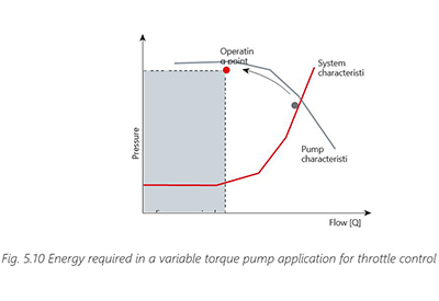
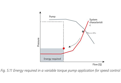
In many fan and pump’s systems, swirl flaps, dampers or throttles are used for controlling the flow of the system. If a centrifugal pump is controlled using a throttle valve, throttling moves the machine’s working point along the pump characteristic. The reduction in energy requirement achieved is minimal compared with the pump’s nominal operating point.
If a fan/pump is speed-controlled, the operating point moves along the system characteristic. This moves the unit out of its best efficiency point and efficiency will typically decrease slightly but the energy saving due to the reduced speed is still much higher compared to throttle or other mechanical controls. In real applications, the achieved energy savings will differ from the theoretical because losses in piping and duct-work result in a basic load and thus additional losses.
In pump applications, often a minimum speed (application and pump type/make- related) is required for avoiding sedimentation of solids and ensuring sufficient lubrication of the pump. If the range between minimum speed and speed for the maximum required power is too big the system can be cascaded. When pumps are cascaded, one speed-controlled pump covers the base load. If consumption increases, the AC drive will switch in more pumps sequentially. The pumps accordingly operate at maximum efficiency whenever possible. Pump control ensures that the system is always as energy-efficient as possible. In some applications more than one pump is speed controlled. Cascades can be used in a similar way for other applications like fans or compressors.
5.4.2 Applications with Constant Torque
Applications with constant torque are applications for which the load is typically not significantly altered by the speed. This includes conveyor belts, hoists and mixers.
If, for example, an engine block is positioned on a horizontal conveyor belt, the weight of that engine block will not change, regardless of the conveyor belt speed. The torque required to move this engine block is always the same. Of course, the friction and acceleration torque would change according to the operating conditions, but the torque needed to move the load remains constant.
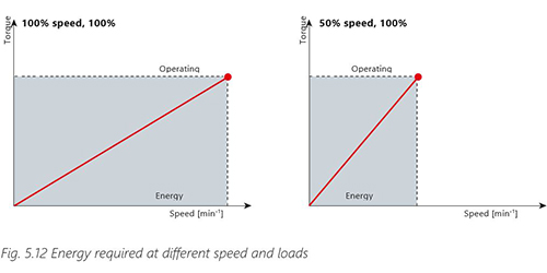
The energy required by such a system is proportional to the required torque and the speed of the motor.
P~T × n
If the speed can be reduced with a constant load as is the case in refrigeration cycles, one of the direct results will be energy savings. In other constant load applications, reduced speed will not have a huge impact. If, for example, the speed of a conveyor belt is reduced, the energy required to transport the goods from A to B stays approximately the same as the distance stays the same. Small savings are achieved through such factors as reduced frictional loss or optimized acceleration. Nevertheless, the use of speed control in constant torque applications is continuously increasing because of the benefits to the process itself.