Facts Worth Knowing about AC Drives – Saving Energy with AC Drives Sections 5.5 – 5.8.2
September 17, 2020
5.5 Life Cycle Costs
Potential ways to save energy can be found in almost all sectors, like building services, conveyor belt systems or chemical processes.
The life cycle costs of an application can be roughly divided into four parts: the initial investment cost, the cost for the operation and maintenance of the application, the cost of the energy required by the application and the disposal cost at the end of the life cycle of the application. The different components are shown in Fig. 5.13.
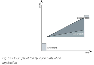
The initial investment costs usually account for only approximately 10% of the overall life cycle costs, whereas in the energy costs can be the largest part of the whole life cycle cost, especially in applications with a high energy consumption. Therefore, the higher initial costs of an energy- saving device often pay for themselves in next to no time.
5.6 System Savings
Successful drive system implementation is based on thorough planning and accurate dimensioning of the drive system. The actual savings are generated during the years of use when the drive system dimensioning and configuration are optimal for the purpose. Each customer has a unique process, which means that each drive system is equally unique and must be designed in accordance with the requirements of the customer’s process.
Regardless of whether the energy efficiency of a new or existing process/machine shall be improved, the whole system must always be considered. Existing installations have the advantage that measurements can be made to determine the losses, creating a benchmark as to whether improvements to the system are working as expected.
Fig. 5.14 illustrates a drive system operating a conveyor showing most of the components which can be found in a drive system. Some of the components are optional.
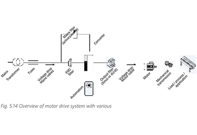
The setup and the whole dimensioning of the system depend on the application (transmission, motor, output filter and motor cable) and its environment (EMC filter, output filters, cables, mains, climate, etc.). Therefore, the engineering and the energy saving assessment should always start with the application assessment. It makes no sense to select one or two highly efficient components if they have a negative impact on the system efficiency. This is illustrated in the following example.
Example:
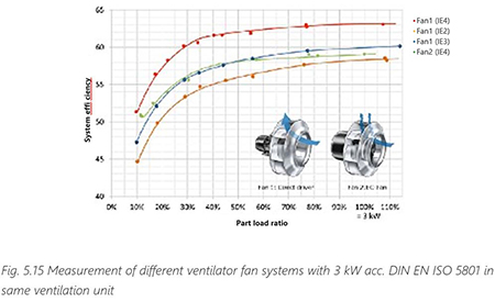
Fan 1 in Fig. 5.15 is a direct-driven type and the system efficiency increases when more efficient motors (better IE class) are used. Fan 2 is an EC fan with a high-efficiency motor. However, as the motor is placed as the hub in the EC fan the air flow is disturbed and the system efficiency decreases. In this case, the fan design leads to lower system efficiency.
Before deciding to make an investment, it is necessary to examine not only the technical, but also the commercial and logistical aspects, so that measures which are not cost-effective, or which are counter-productive, can be avoided or minimized. TCO (Total Cost of Ownership
= total costs within a certain timeframe) and LCC (Life Cycle Costs = costs incurred within a lifecycle) are methods used for such an evaluation.
A life cycle cost analysis includes not only the procurement and installation costs, but also the costs of energy, operation, maintenance, downtime, the environment and disposal. Two factors, energy cost and maintenance cost, have a decisive effect on the life cycle cost.
LCC = Cic +Cin + Ce + Co + Cm + Cs + Cenv + Cd
Cic = initial capital cost (procurement cost) Cin = installation and commissioning costs Ce = energy cost
Co = operating cost
Cm = maintenance cost
Cs = downtime and lost production costs Cenv = environmental cost
Cd = decommissioning and disposal costs
One of the biggest factors in the life cycle cost formula is the energy cost. Higher investments which bring the energy consumption down will, in many applications, have a major impact on energy costs in the long run.
5.7 Using Regenerated Power
Electric motors can be operated in generative mode when the torque is in opposite direction than the speed (II and IV quadrant operation – see Chapter 4.5). This can happen when decele- rating the motor from one speed to another. In such a situation, the energy will flow from the motor to the drive. This energy needs to be somehow dissipated. In practice this can be done in three ways:
- injecting the energy back to the electricity grid (regenerating)
- using the energy in other drives connected together in the DC circuit (load sharing)
- burning the energy in a brake resistor
The choice of the right solution depends on several factors. The cheapest solution is load sharing, but its applicability depends on the application, if there are multiple drives in the application where some are motoring while others are generating. Using brake resistors is a bit more expensive and the energy is wasted. In many situations, especially for lower powers, this is acceptable. Regenerative drives (also known as Active Front End – AFE, Active Infeed Converters – AIC or Four Quadrant Converters, are more expensive.
Whether the use of regenerative drives is economic depends on 3 factors:
1. Available energy
Most applications generate energy during deceleration processes. This energy decreases continuously during the speed change. Theoretically, the regenerated energy is 100% of the difference between the energy which is in the system when starting and stopping the deceleration, but in reality, this figure lies somewhere between 10 and 20%. Exceptions to this are seen in lifts, cranes and hoists – in general in vertical movement operation. Furthermore, the nominal motor performance is not equal to the regenerated energy as oversizing of motors is common practice. Only very rarely does the nominal motor power hit exactly the required application power.
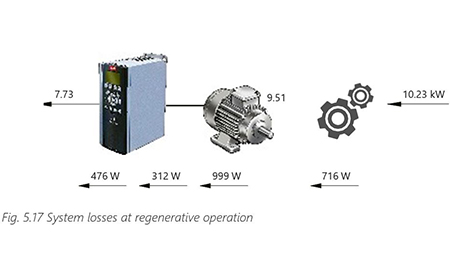
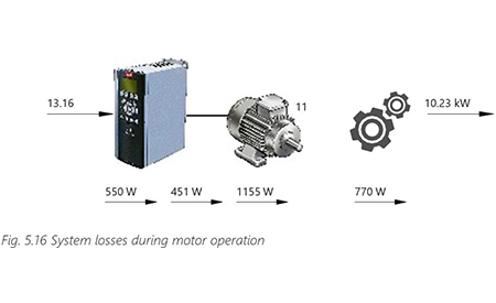
2. Losses
Motor, cables, gears and even the AFE itself create losses that reduce the energy which can be fed back into the grid. The losses caused by the AFE itself are higher than for a standard AC drive due to the active rectifier whose losses can be twice as high in operation but also in standby. Also, to prevent higher losses in the grid due to switching noise, an AFE requires a filter on the input side.
3. Occurrence
The more often the motor is operated in regenerative mode the more energy is fed back to the grid. Therefore, situations during a load cycle where energy is generated must be considered. As well as the load cycle itself, the number of load cycles defines the resulting amount of energy for a given time.
5.8 Hybridization
Hybridization refers to the combining and using of multiple energy sources to deliver power while maximizing efficiency. The idea behind hybridization is to solve issues in power demand in the most cost effective and suitable manner. This is done by introducing a means of energy storage into the system, such as batteries, super capacitors, flywheels, pumped hydro or compressed air.
The most commonly used of these are lithium-based batteries, such as lithium-ion or lithium- polymer batteries. Battery storage is often chosen in applications like back-up power due to the ability to store and deliver a charge for a fairly long period of time. Battery prices are falling quickly, driven by the growth of the hybrid and full-electric automotive industries, and followed closely by the renewable energy market. This means that, in a relatively short time, batteries will be made more viable and cost effective for customers looking to migrate to hybrid systems in their applications.
Energy storage is often described as a key enabler for integrating renewable energy into power generation. However, by equipping both machines and entire processes with energy storage systems, it is also possible to significantly improve power quality and upgrade performance and overall efficiency. Energy storage provides greater stability in power production systems by applying peak shaving to the incoming power, time shift for production and back-up power in emergency situations.
Time shifting
Time shifting involves storing energy during times when energy costs from the grid are low and supplying energy from the storage medium when energy costs from the grid are high.
Peak shaving
Peak shaving involves optimizing the energy flow between the incoming supply and local storage to meet spikes in demand. Excess energy can be stored when demand and costs are low.
Back-up power
Energy storage can be used to provide back-up power during outages maintaining the ability to operate for a period of time.
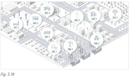
Typical applications where hybridization solutions are used:
- – Solar and wind power
- – Energy production
- – Grid and substation
- – Marine and offshore industry
- – Harbors
- – Process industry
- – Commercial buildings
- – Transportation
- – Land construction & Mining
AC/DC grid converters and DC/DC converters are used to connect energy storages into AC or DC grids. In a centralized energy storage, the energy storage is connected to the AC grid using a grid converter. The energy storage can then be used by all the loads connected to the AC grid. The grid converter is used to convert the DC voltage of the energy storage to match the voltage and frequency of the AC grid.
In an integrated energy storage, the energy storage is brought closer to the load and used to supply a single application. The energy storage can be connected straight to the DC-link or common DC bus through a DC/DC converter. The DC/DC converter is needed to convert the DC voltage from the energy storage to the DC voltage of the DC-link.
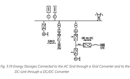 5.8.1 Grid Converter
The grid converter enables bidirectional transformation between DC and AC voltage. The converter can supply power to the AC grid from the battery or charge the battery from the AC grid.
The main components of the grid converter are an inverter unit, an LC filter and a transformer. The filter and transformer are required on the AC grid side to ensure AC power quality when supplying power to the AC grid and to have an optimal voltage for charging the battery. The transformer is also required to ensure that there is no common-mode voltage supplied to the battery.
The grid converter has a floating DC voltage on the battery side. The voltage is defined by the state of charge and load on the battery. The battery voltage can vary, but it does need to be between the minimum and maximum DC voltages which the DC-link of the drive can handle.
5.8.2 DC/DC Converter
The DC/DC converter works as a bidirectional voltage controller between the battery and the DC-link or common DC bus. Power can be supplied from the battery to the DC-link or the battery can be charged from the DC-link.
The voltage of the used battery does not need to match the DC-link voltage. The voltage can vary greatly depending on the charge of the battery and the load on the battery, but the maximum voltage of the battery must be slightly lower than the DC-link voltage.
The DC/DC converter includes an inverter unit and individual chokes for each phase on the battery side. The chokes minimize the ripple on the DC current supplied from the drive to the battery. The chokes are also used to enable the feeding of current from the lower battery voltage to the higher DC-link voltage (through DC boosting).