Facts Worth Knowing about AC Drives – Star and Delta Configuration in Field Weakening Operation Sections 4.1 – 4.4.7
July 27, 2020
In the previous chapters, the motor and the AC drive were each presented in isolation. This chapter explains the interaction between the two components.
4.1 Basic Principles
4.1.1 U/f Operation and Field Weakening
The major technical characteristics of a motor are found on its nameplate. The information shown is very relevant for the electrical installer because values for voltage, frequency and full load current are given, but important information for the mechanical design is missing and can be found in the datasheet, catalogue, or by direct contact to the motor manufacturer.
This mechanical design information includes data related to motor start and intermittent operation, and also the available torque at the motor shaft. The shaft torque is easy to calculate from the nameplate data.
For a given load, the following expression applies:
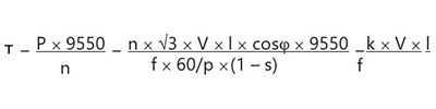
This results in the principle relation:
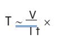
This relation is utilized in voltage source AC drives which maintain a constant ratio between the voltage (U) and the frequency (f ). This constant ratio (U/f ) determines the magnetic flux density (Φ) of the motor and is determined by the motor nameplate data (for example, 400 V/50 Hz = 8 V/Hz). The constant flux density ensures optimum torque from the motor. Ideally the ratio 8 V/Hz means that each 1 Hz change in the output frequency will result in an 8 V change in the output voltage. This way of controlling the output values of the AC drive is called “U“ to “f” characteristic control.
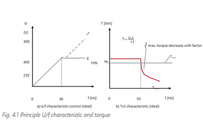
The ideal curve of the U/f characteristic for a star connected 50 Hz motor is shown in Fig. 4.1 Principle U/f characteristic a) applied motor voltage b) resulting torque. Up to 50 Hz the AC drive applies a constant U/f ratio to the motor which result in the possibility to get a constant torque out of the motor.
For operating the motor at 100 Hz ideally the output voltage should be increased to 800 V to maintain a constant U/f ratio (dotted line in Fig. 4.1a Principle U/f characteristic and torque). As this high voltage is critical for the motor insulation this is not an applied strategy. Typically, the AC drive limit its output voltage to the value of the input (for example 400 V ±10%)
This means that the AC drive can maintain a constant U/f ratio to a certain frequency only. After this frequency it can continue to increase the frequency but not the voltage anymore. As this
is affecting the U/f ration the magnetic flux density is reduced. Therefore, this speed range is also called field weakening area (Fig. 4.1 Principle U/f characteristic and torque). The reduced magnetic field results in a reduced maximum motor torque. While the nominal torque is reduced by 1/f the stall torque decreases by 1/f2.
Please note that the shown curves are ideal and require some compensation which are described in the following sections.
4.1.2 Star and Delta Configuration in Field Weakening Operation
Typically, induction motors operated with AC drives are connected to the nominal voltage of the mains. This means that a 400 V/230 V motor will be configured in a star when operated by a 400 V drive. As described in the previous section a 50 Hz motor will enter field weakening
when the voltage can’t be increased any more. For extending the speed range the motor can be configured in delta.
Example
Motor: 15 kW, 400 V/230 V Y/Δ, 27.5 A/48.7 A, 50 Hz
At 50 Hz the power in star and delta configuration is 15 kW because of the different mains voltage which result in different motor currents.
PY (50 Hz) = Ö3 x 400 V x 27.50 A x cos φ x η = 14.92 [kW]
PΔ (50 Hz) = Ö3 x 230 V x 48.70 A x cos φ x η = 15.19 [kW]
With delta connection it can be seen in Fig. 4.2 87 Hz characteristic that in contradiction to the star configuration the motor runs with constant U/f ratio up to 230 V, but if the AC drive is powered from a 400 V supply, we are actually able to keep the constant U/f ratio up to 400 V and the high current, PΔ (87 Hz) = Ö3 x 400 V x 48.70 A x cos φ x η = 26.42 [kW].
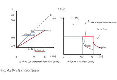
This means we have the rated flux density (Φ) up to 400 V even when the motor is configured for 230 V. With this higher voltage we can increase the maximum frequency with rated flux to 87 Hz.
The use of this knowledge presupposes the following:
- – The selected AC drive must easily be able to handle the higher delta current (48.70 A)
- – The motor must be wound such that it can withstand the required operating voltage (typically higher in the star configuration) supplied by the AC drive (i.e. with a 690 V supply voltage and a 690 V drive, this application is only possible with a motor wound for 690 V / 400 V Y/Δ)
- – The torque on the motor shaft remains the same for both configurations up to 50 Hz. Above 50 Hz, a star-connected motor enters the field weakening range. When it is delta-connected, this does not happen until approximately 90 Hz. If the ±10% tolerance of the AC drive is used, the field weakening range begins at 55 Hz or 95 Hz respectively. The torque decreases because the motor voltage is not increased
The benefits of this increased motor capacity utilization are:
- – An existing AC drive can be operated with a greater speed control range
- – A lower-power rating motor can be used. Such a motor can have lower moment of inertia which allows higher dynamics. This improves the dynamic characteristics of the system
The disadvantages of this increased motor capacity utilization are:
- – The higher speed will shorten the lifetime of the bearings or will require bearing lubrication at shorter intervals
- – A lower-power rating motor means that the bearings are smaller and less mechanical load is allowed
Please note that operation of a 400V/230V Y/Δ motor in delta at 400 V is only possible on an AC drive because of the higher feeding frequency of 87 Hz. Operation direct on 400 V/ 50 Hz mains will destroy the motor.
4.1.3 Running in Current Limit
As seen, the relationship between motor shaft torque and motor current indicates that if motor current can be controlled, then the torque is also under control. If an application temporarily needs torque up to maximum it is essential that the AC drive is designed for continuous operation current up to the current limit, and not exceed it or trip.
There are different strategies for designing the AC drive to run in current limit situations. The most typical strategy is the fact that torque will be reduced when the speed is reduced. But as we shall see later there can be applications where this strategy cannot be utilized and can even cause bigger problems.
4.2 Compensations
It used to be difficult to tune an AC drive to a motor because some of the compensation functions, such as “start voltage”, “start compensation” and “slip compensation”, are difficult to relate to practice.
These compensations are required because motor characteristics are not linear. For example, an induction motor requires a greater current at low speed to accomplish both magnetizing current and torque-producing current for the motor. The built-in compensation parameters ensure optimum magnetization and hence maximum torque:
- • During start
- • At low speeds
- • In the range up to the rated speed of the motor
In the latest generation of AC drives, the device automatically sets the necessary compensation parameters once the motor rating details of the motor have been programmed into the AC drive. These details include voltage, frequency, current and speed. This applies to approximately 80% of standard applications such as conveyors and centrifugal pumps. Normally, these compensation settings can also be changed manually for fine tuning applications such as hoisting or positive displacement pumps if required.
4.2.1 Load-independent Start Compensations
Increase, if necessary, the output voltage in the lower speed range by manually setting an additional voltage, often called start voltage.
Example
A motor which is much smaller than the recommended motor frame size of an AC drive may require an additional, manually adjustable voltage boost in order to overcome static friction or ensure optimum magnetization in the low speed range.
If several motors are controlled by one AC drive (parallel operation), it is recommended to de- activate the load-independent compensation.
The load-independent supplement (start voltage) ensures an optimum torque during start.
4.2.2 Load-dependent Start Compensations
The load-dependent voltage supplement (start and slip compensation) is determined via the current measurement (active current).
This compensation is normally called the I x R compensation, boost, torque increase, or, at Danfoss, start compensation.
This type of control reaches its limits when the disturbances are difficult to measure, and the load is highly variable (for example in motors with operational change in the winding resistance of up to 25 % between the hot and cold states).
The voltage increase may have different results. Under no-load operation, it may lead to saturation of the stator and rotor material. In the event of saturation, a high reactive current will flow that leads to heating of the motor. If the motor is operating with a load, it will develop little torque because of the weak main flux and may stop running. The real U/f and T/n characteristics are generally as shown in Fig. 4.3 Real U/f and T/n characteristic.
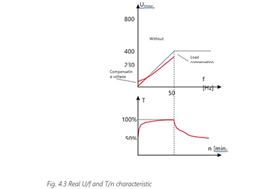
In Fig. 4.3, additional voltage is supplied to the motor at low speeds for the purpose of compensation.
4.2.3 Load Compensations
The motor voltage is increased under load ascertained from the measured motor current. The output voltage receives a voltage boost which effectively overcomes the influence of the DC resistance of the motor windings at low frequencies and during start.
An increase in output voltage which is too high compared to the U/f characteristic leads to over- magnetization of the motor. This increases the thermal load on the motor such that a reduction in torque is to be expected. The motor voltage is reduced in no-load operation.
4.2.4. Slip compensation
The slip of an induction motor is load-dependent and typically amounts to some 5% of the rated speed (less than 1% for larger motors). For a two-pole motor, this means that the slip will be around 150 RPM.
However, the slip will be approximately 50% of the required speed if the AC drive is controlling a motor at 300 RPM (10 % of the rated synchronous speed of 3000 RPM).
If the AC drive has to control the motor at 5 % of the rated speed, the motor will stall if it is loaded. This load dependence is undesirable, and the drive can fully compensate for this slip by effectively measuring the active current to the motor.
The AC drive then compensates for the slip by increasing the frequency according to the actual measured current. This is called active slip compensation.
The AC drive calculates the slip frequency (fslip) and the magnetization or no-load current (I) from the motor data. The slip frequency is scaled linearly to the active current (difference between no-load and measured current).
Example
A 4-pole motor with a rated speed of 1455 RPM has a slip frequency of 1.5 Hz and a magnetization current of approximately 12 A. With a load current of 27.5 A and 50 Hz, the AC drive will output a frequency of about 51.5 Hz. At a load current between I (12 A) and IN (27.5 A), the frequency will be adjusted accordingly between zero and 1.5 Hz.
As demonstrated in the example, factory setting of slip compensation is often scaled such that the motor runs at the theoretical synchronous speed. In this case, 51.5 Hz – 1.5 Hz = 50 Hz.
4.2.5 PM Motor and SynRM Compensations
For Permanent Magnet motors the start and slip compensations are irrelevant, but other parameters are essential.
The magnetizing profile differs of course from the induction motor, but other important data and compensations are:
- • Nominal motor speed and frequency
- • Back EMF
- • Max speed before back EMF damages the AC drive
- • Field weakening
- • Dynamic details relevant for the control
For SynRM motors other parameters are essential, for instance:
- • Stator resistance
- • d and q axis inductances
- • Saturation inductances and
- • Saturation point
4.3 Danfoss Automatic Motor Adaptation (AMA)
Motor data on the motor nameplate or from the motor manufacturer’s datasheet are given for a specific range of motors, or a specific design, but those values rarely refer to the individual motor. Due to variations in the production of motors and the installation, those motor data are not always accurate enough to ensure optimal operation.
Also, as seen previously there are several compensations which require setting. For modern AC drives, fine-tuning to the actual motor and installation can be a complicated and troublesome task.
To make installation and initial commissioning easier, automatic configuration functions like the Automatic Motor Adaption (AMA) from Danfoss are becoming increasingly common. These functions measure for example the stator resistance and inductance. The effect of the cable length between AC drive and motor is also taken into account.
The parameters required for different motor types differ in important details. For instance, the back-EMF value is essential for PM motors and saturation point level is important for SynRM motors. Therefore, different types of AMA are required. Note that not all AC drives support the motor identification function for all motor types.
In principle two strategies are used to measure relevant motor parameters:
Dynamic
The function accelerates the motor to a certain speed to perform the measurements. Typically, the motor must be disconnected from the load/machine for an “identification run”.
 Static
The motor is measured at standstill. This means there is no requirement to disconnect the motor shaft from the machine. It is important, however, that the motor shaft is not rotated by external influences during measurement.
4.4 Operation
4.4.1 Motor Speed Control
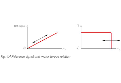
The output frequency of the AC drive, and thus the motor speed, is controlled by one or more signals (0-10 V; 4-20 mA, or voltage pulses) as a speed reference. If the speed reference increases, the motor speed goes up and the vertical part of the motor torque characteristics is shifted to the right (Fig. 4.4 Reference signal and motor torque relation).
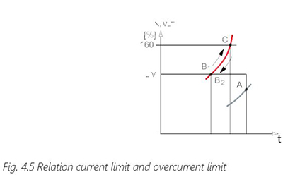
If the load torque is less than the motor torque, the speed will reach the required value. As shown in Fig. 4.5 Relation current limit and overcurrent limit, the load torque curve intersects the motor torque curve in the vertical part (at point A). If the intersection is in the horizontal part (point B), the motor speed cannot continuously exceed the corresponding value. The AC drive allows brief current limit overshoots without tripping (point C), but it is necessary to limit the duration of the overshoot.
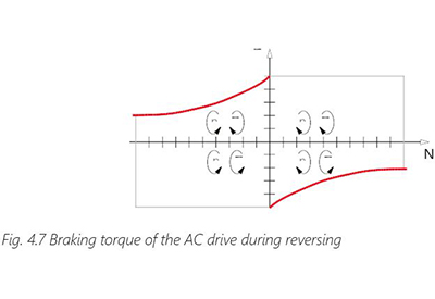
4.4.2 Reversing
The direction of rotation of asynchronous and many synchronous motors is determined by the phase sequence of the supply voltage. If two phases are swapped, the direction of rotation of the motor changes (the motor reverses).
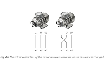
An AC drive can reverse the motor by electronically changing the phase sequence. Reversing is accomplished by either using a negative speed reference or a digital input signal.
If the motor must have a specific direction of rotation when first put into service, it is important to know the factory default setting of the AC drive. In some cases, reversing can even damage the motor, so typically reversing is disabled by default.
Since an AC drive limits the motor current to the rated value, a motor controlled by a drive can be reversed more frequently than a motor connected directly to the mains.
4.4.3. Acceleration and Deceleration Ramps (Ramp Up and Down)
For many applications there are various reasons why the speed must not change too quickly but instead must be changed slowly or with smooth transitions. All modern AC drives have ramp functions to facilitate this. These ramps are adjustable and ensure that the speed reference is able to increase or decrease only at a preset rate.
The acceleration ramp (ramp up) indicates how quickly the speed is increased. It is stated in the form of an acceleration time tacc and indicates how quickly the motor should reach the new speed. These ramps are mostly based on the rated motor frequency, e.g. an acceleration ramp of 5 seconds means that the AC drive will take 5 seconds to go from standstill to the rated motor frequency (fn = 50 Hz).
However, there are some manufacturers who relate the acceleration and deceleration to the values between the minimum and maximum frequency.
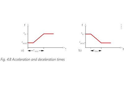
The deceleration ramp (ramp down) indicates how quickly the speed is decreased. It is stated in the form of a deceleration time tdec and indicates how quickly the motor should reach the new reduced speed.
It is possible to go directly from acceleration to deceleration since the motor always follows the output frequency of the inverter.
Ramp times can be set to such low values that in some situations the motor cannot follow the preset speed.
This leads to an increase in the motor current until the current limit is reached. In the case of short ramp-down times, the voltage in the intermediate circuit may increase to such a level that the protective circuit will stop the AC drive.
If the inertia of the motor shaft and the referred inertia of the load are known, the optimum acceleration (tacc) and deceleration (tdec) times can be calculated.
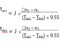
J is the moment of inertia of the motor shaft and load [kgm2].
Tfric is the friction torque of the system [Nm].
Tacc is the overshoot torque used for acceleration [Nm].
Tdec is the braking torque that occurs when speed reference is reduced [Nm]. n1 and n2 are the speeds at frequencies f1 and f2 [min-1].
If the AC drive allows an overload torque for a brief time, the acceleration and deceleration torques are set to the rated motor torque T. In practice, the acceleration and deceleration times are normally identical.
Example
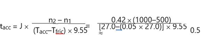
A machine has the following specifications:
J = 0.42 kgm2
n1 = 500 min-1
n2 = 1000 min-1
Tfric = 0.05 x TN
TN = 27 Nm
Theoretical acceleration time can be calculated as follows:
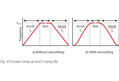
The ramp functions ensure that there is no abrupt change of speed, provided the AC drive is set to the calculated acceleration. This is essential for many applications like:
- – Ensuring bottles do not topple over on bottle transporting conveyors
- – Preventing water hammer in pump systems
- – Ensuring comfort in escalators or lifts
Most often linear ramps are used. However different characteristics are possible for different applications, for example, an “S” or “S2” ramp. With the “S” ramp, the transitions to and from standstill are particularly gentle.
4.4.4 Motor Torque Control
Motor torque is another parameter which is important for the application, as shown in Fig. 4.5 The motor current can overshoot the current limit briefly.
Torque is the basis for the rotation or movement of a load. Reasons for controlling the torque include:
- • Limiting the torque to prevent damage on machine etc.
- • Control the torque to make more motors share the load.
If an application is suddenly overloaded, and the AC drive is sized for overload, the machine can work for a given time in the overload mode. However, this excessive torque can be fatal for the machine or reduce the lifetime. Therefore, many AC drives can be programmed to send a warning in case of overload, but also limit the torque under specific conditions.
As described in section 4.1 Basic Principles there is a relationship between current and torque. This relationship is not direct, but depends on slip, cos phi and temperature in the motor. The limitation based on measuring the current is not accurate. If the AC drive is the Space Vector type or the flux type (see chapter 3 AC drives) the current is measured vectorially in all three motor phases, and the distribution of the current components is easy. With this information the AC drive can calculate the torque precisely enough to make sure the machine is protected.
In situations where more motors are on a common mechanical system, it is essential that the motors share the load equally. If the slip compensation factor is reduced, the motors will automatically balance their torque, but not necessarily maintain the desired speed.
Another function in some AC drives is called the Droop function. Droop function means that one motor is controlling the speed and additional drives follow the same speed and automatically share the load.
Example
A 100-meter-long conveyor belt has numerous drive stations distributed along the belt. If one of the motors tends to run a bit faster than the other, this motor will have to give more torque. The result can be:
- • The motor can be overloaded and overheated
- • The belt can be damaged because of the partially higher torque
- • Pulleys and drive drums may slip with excessive wear as result In such situations, torque and torque sharing is important.
4.4.5 Watchdog
AC drives can monitor the process being controlled and intervene in case of operational disturbance. This monitoring can be divided into three areas: machinery, motor and AC drive.
The machinery is monitored by
- • Output frequency
- • Output current
- • Motor torque
Based on these values, a number of limits can be set which intervene in the control function if they are exceeded. These limits could be the lowest permissible motor speed (minimum frequency), the highest permissible motor current (current limit) or the highest permissible motor torque (torque limit). If the limits are exceeded, the AC drive can, for example, be programmed to:
- • give a warning signal,
- • decrease the motor speed or
- • stop the motor as fast as possible
Monitoring a drive can be used to predict possible problems before they occur and plan preventive maintenance accordingly. This enhances the availability of the drive, reduces the risk of failure and lowers costs.

Example
In an installation using a V-belt as a connection between the motor and the rest of the installation, the AC drive can be programmed to monitor the V-belt. If the V-belt were to slip or brake, the AC drive would detect the sudden decrease in the motor torque and can be programmed to either give a warning or stop the motor.
4.4.6 Energy Efficient Motor Start
The energy for starting a motor can be split into 3 major parts:
- • Energy required for operating the load
- • Energy required for accelerating the load and the motor
- • Losses in motors and control
The simplest way for starting a motor is to connect the motor direct on line (DOL) but this is also an inefficient solution. The motor will have high losses when starting due to the huge slip when applying the voltage. While accelerating the motor, the slip and hence the losses are reduced.
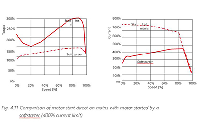
Softstarters can be used which adjust the motor voltage like Star/Delta starters, but linearly. The device increases the voltage until a programmed current limit is hit. The limit is application- dependent, typically in the range of 300-500% FLC. While the motor is accelerating the current drops and the device increases the voltage further. This sequence continues until the mains voltage level is applied to the motor.
For minimizing the losses Softstarters are typically operated in by-pass after the motor has been started. During the starting phase the losses are approximately 4.5 W per A.
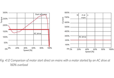
The most efficient way for starting a motor is the use of AC drives. As voltage and frequency are controlled the slip and hence the losses are reduced. Using a by-pass like on Softstarters is possible but seldom used.
Principle torque and current curves for starting a motor with constant load direct on mains, by a softstarter and by an AC drive are shown in Fig. 4.11 Comparison of motor start direct on mains with motor started by a softstarter and Fig. 4.12 Comparison of motor start direct on mains with a motor started by an AC drive at 160% overload. The curves will look different with different loads.
4.4.7 Energy Efficient Motor Control
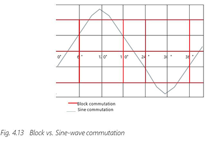
All motors operate by applying the correct voltage at a given frequency. A rotating shaft does not mean, however, that the motor is operating efficiently. For controlling a motor, a control algorithm (U/f, voltage vector, flux vector…) and a control strategy are required. That both components must suit a motor type can easily be seen with motors using permanent magnets. For energy-optimum operation the controller must match the supply voltage waveform as closely as possible to the waveform of the back EMF. Block commutation is used for trapezoidal back EMF and sine commutation for sinusoidal.
Block commutation is known to have some disadvantages like torque ripple and excessive noise. However, both technologies are comparable when it comes to efficiency.
Control strategies which are often used in different control algorithms are:
Constant Torque angle
Maximum torque is created when the torque angle is kept constant at 90°. The constant Torque angle strategy keeps the angle constant by controlling the rotor d-axis current to zero while leaving the current vector on the y-axis.
Maximum Torque Per Ampere
This strategy minimizes stator current magnitude for a required torque while considering reluctance torques. Variations in inductances during operation must be considered to obtain best results.
Constant Unity Power Factor control
The angle between current and voltage vector is kept constant under this strategy so the apparent power rating of the inverter can be reduced.
In addition, AC drives provide extra functionalities for reducing the magnetic field strength at reduced load. This can be done by special U/f characteristics or by Automatic Energy Optimization (AEO) functions.
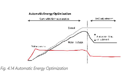
Automatic adjustments take place after the application reaches a steady state. The applied control strategy reduces the magnetization level and thus the energy consumption. An optimized balance between energy saving and having enough magnetization for sudden load peaks must be given to ensure reliable operation. See fig 4.14 Automatic Energy Optimization.
The average energy saving potential for small to medium-sized drives is 3 to 5 % of the rated motor power during operation at low loads. As a very important side-effect, the motor runs almost noiselessly at low loads – even at low to medium switching frequencies.