Facts Worth Knowing about AC Drives – Electromagnetic Compatibility Sections 6.5 – 6.7
November 4, 2020
6.5 Output filters
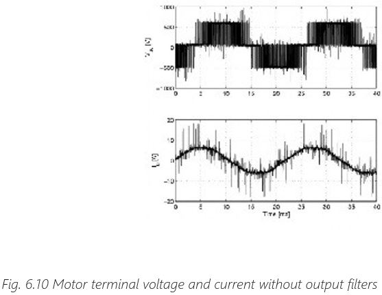
Variable speed drives, due to their operating principle, produce a series of unwanted secondary effects, such as: motor winding isolation stress, bearing stress, acoustic switching noise in the motor and electromagnetic interference. In most applications these effects are at an acceptable level – but in some cases these effects need to be mitigated. For the mitigation of these effects, filters are installed at the output of the drives. The most commonly known filters are dU/dt filters, sine-wave filters and common-mode filters.
6.1.1 dU/dt filters
dU/dt filters can have various circuit configurations, but are typically LC filters (sometimes also with damping resistors) with a cut-off frequency tuned above the switching frequency of the drive.
As their name suggests, dU/dt filters reduce the slew rate of the voltage pulses at the drive output to rates which are typically below 500 V/µs. This will reduce the stress of the motor winding isolation. The voltage shape remains pulse-width modulated.

There are various standards setting limits for the rise-time and peak voltage values at the motor terminals. The definition of rise-time is slightly different between international IEC standards and the American NEMA recommendation, as shown in the picture below.
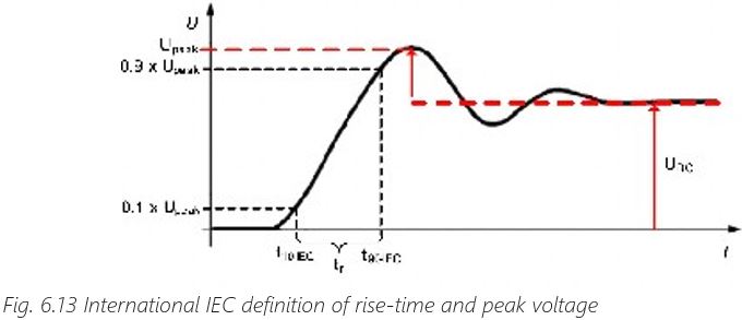
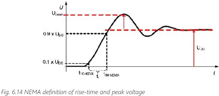
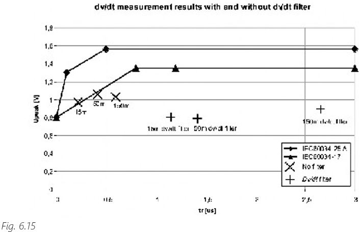
The dU/dt filters increase the rise-time and help complying with the relevant standard. An example can be seen in the graph below:
dU/dt filters are recommended in applications with old motors with poor isolation, or in applications where the supply voltage is 690 V. In applications with short motor cables, dU/dt filters can be used for reducing the dU/dt. But in applications with long motor cables, dU/dt filters no longer make sense, because the cable itself will act as a filter and reduce the dU/dt rate at the motor terminals.
6.1.2 Sine-wave Filter
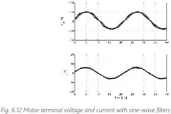
A sine-wave filter is a LC low-pass filter, whose cut-off frequency, unlike that of a du/dt filter, is set to eliminate all the high frequency components of the AC drive’s output voltage. It produces a near perfect sinusoidal voltage waveform.
With a sine-wave filter, the voltage stresses on the motor correspond to those existing in normal direct-on-line (DOL) use with a power source of the same voltage. A sine-wave filter is suitable especially for old motors not designed to be used with AC drives.
A sine-wave filter eliminates bearing currents and voltage reflections, and it also reduces a motor’s noise levels. If an output transformer is used, the sine-wave filter eliminates high- frequency components that could stress the transformer. The sine-wave filter also allows the use of considerably longer motor cables.
Sine-wave filters are much more expensive than du/dt-filters. This is because the desired frequency characteristics require the use of larger inductance and capacitance.
The sine-wave filter typically causes a 7-10% voltage drop. This may require boosting the output voltage of the AC drive. Also, when used in the field weakening range, the pull-out torque drops faster (than without a sine-wave filter).
6.1.3 Common-mode Filter
Common-mode filters are used to reduce bearing and ground currents, but it does not provide any significant du/dt filtering.
High-frequency common-mode filtering can be achieved using toroidal cores of nanocrystalline material to provide a higher inductance. A cable carrying a current has a magnetic field around it. The effect of the ferrite is to concentrate this field and, hence, to increase the cable’s inductance by several hundred times.
If a ferrite is put on to a cable which includes all three phases, it will have no effect on the differential-mode current, but it will increase the impedance of common-mode currents. This is because the differential currents, by definition, sum to zero and therefore there is no net magnetic field. The common-mode currents produce a net magnetic flux and this flux is concentrated in the bulk of the ferrite, resulting in an increased impedance for common-mode currents only.
This is also why only phase conductors are slipped through the rings. The PE conductor must be separated. All ferrites are conductive, so it is important that cables passing through them are sufficiently well insulated. Also, the common-mode filter should be installed directly after the drive output before any other output filters.
6.6 Bearing electric stress
When the motor is rotating at normal speed, the bearings isolate the stator from the rotor. This happens because a thin film of lubricant comes in between the bearing races and the bearing balls. The thickness of the isolating lubricant film is in the range of 0,5 µm, therefore a voltage as low as 10 V can cause a breakdown of the isolation and an electrical discharge. When a discharge occurs, the metal of the bearing races and bearing balls is melted, causing a microscopic pit. The accumulation of pits in time is called pitting, and the process of deteriorating the metal of the bearings is called electrical discharge machining, shortly EDM.
While EDM has been known for almost a century (scientific papers report on this phenomenon already in the 1920’es), with the increased use of variable speed drive the occurrence of EDM seems to increase. While some of the causes can be attributed to mechanical factors (motor not designed for variable speed operation, insufficient cooling at lower speeds, prolonged operation at low speeds, etc.), the main cause leading to the increase of EDM is the increase of motor shaft voltage when a variable speed drive is used.
The root cause of shaft voltage is the steep switching rate of the drive output voltage (commonly known as dU/dt) combined with the inherent common-mode voltage produced by the output stage of the drive (inverter). Other factors leading to shaft voltage are independent of the use of drives, such as motor asymmetries or the use of asymmetric motor cables – especially in high-power applications where the motor current exceeds 100 – 200 A.
There are various mechanisms of coupling voltage to the motor shaft:
- – Capacitive coupling – Caused by capacitive coupling of the common-mode voltage with high dU/dt between stator winding and rotor
- – Inductive coupling – Caused by magnetic coupling of circulating currents between stator circulating currents and rotor circulating currents
What to do in the case of bearing failures?
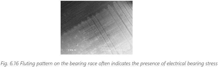
When bearing failures occur, the appearance of a “fluting” pattern on the bearing often indicates the presence of electrical bearing stress. If the bearing is analyzed with an electron scanning microscope, the pits produced by electric discharges become visible.
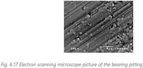
Before taking corrective actions, it is important to determine the root cause of the bearing failure. Bearing analysis consists of visual inspection, electron microscope imaging and a chemical analysis of the lubricant.
Bearing failures can have mechanical root causes and electrical root causes. Mechanical root causes are the most frequent, but they are often handled incorrectly by interpreting them as electrical faults. Indeed, when the root cause is mechanical, the electric discharges will accelerate the wear-out. In such cases, mitigating the electric stress will extend the life time but not fix the root cause. Mechanical root causes need to be mitigated mechanically first.
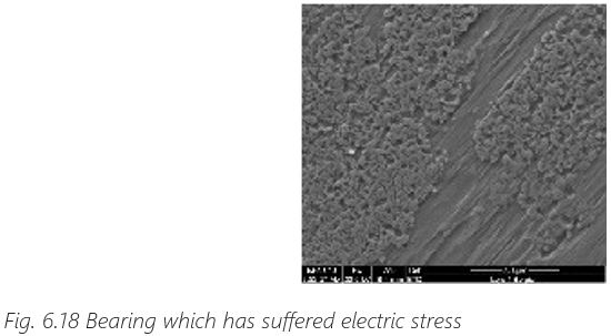
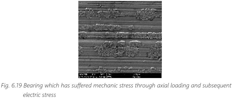
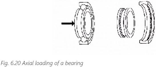
The following pictures (taken with electron microscope) show examples of bearings which have suffered damage. The first picture shows a bearing that has suffered electric stress – in this case an electric measure is needed. The second picture shows a bearing that has suffered mechanical stress through incorrect axial loading. The parallel trenches in the metal have been caused by the incorrect load. But near the trenches, pitting can be seen – a sign that the damage started mechanically but was accelerated by electric stress.
Mechanical mitigation measures
- – Make sure that the motor and the load are properly aligned
- – Make sure that the mechanical loading of the bearing (radial and axial) is within specifications
- – Check the vibration level
- – Check the grease of the bearing and make sure the bearing is correctly lubricated for the given operating conditions
Electric mitigation measures
- – Provide a low-impedance return path to the high-frequency currents
- – Follow EMC installation rules strictly, for example by using a shielded cable between drive and motor, and connecting the shield at both ends with a proper high-frequency connection
- – Make sure the motor is properly grounded and the grounding has a low impedance for high frequency currents
- – Provide a good high-frequency grounding between motor chassis and load
- – It is possible to use shaft grounding brushes for eliminating the shaft voltage
- – Use symmetrical motor cables, especially in high power applications where the motor current exceeds 100 – 200 A
- – Use common-mode filters for reducing the high frequency currents between drive and motors
High frequency common-mode filters are a good solution for reducing electric bearing stress, but the use of such filters does not eliminate the need of an EMC-correct installation.
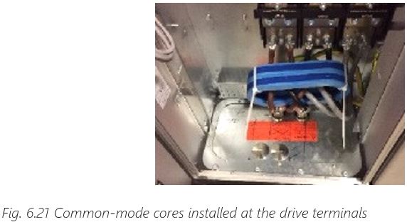
High-frequency common-mode filters consist of magnetic cores built using highly permeable magnetic material (nanocrystalline core). The three motor phases pass through the cores – it is absolutely necessary to follow the correct mounting instructions. Not passing all motor phases through the cores will lead to core saturation, or passing also the shield of the cable will deem the cores ineffective.
The high frequency cores can be installed either at the drive terminals or in the motor terminal box. When installed at the drive terminals, the cores will also reduce high frequency noise in the motor cable. The disadvantage of installing at the drive terminals is that the capacitive currents through the long motor cable can saturate the cores. The mounting of the cores in the motor terminal box eliminates the risk of core saturation. But in this case there will be no reduction of the electromagnetic noise from the motor cable.

6.7 European EMC Directive and EMC Standards
European EMC Directive
The latest EMC Directive is 2014/30/EU, which came into force on the 20th of April 2016 replacing the previous directive 2004/108/EC. This directive is a legal requirement in the European Union. In essence the requirements are simple:
- Products must not emit unwanted electromagnetic interference (limits emission)
- Products must be immune to a reasonable amount of interference (sets immunity requirements)
The directive itself is a political document and gives no specific technical requirements. A producer has the possibility of using harmonized standards to demonstrate compliance with the directive. Compliance with the EMC Directive (and also with other relevant directives such as the Low Voltage Directive – LVD) is stated in the product’s Declaration of Conformity and the “CE” mark is affixed to the product.
The scope of the EMC Directive consists of the following two categories:
- – Apparatus: a finished appliance made commercially available as a single-function unit and intended for the end user. Apparatus complying with the requirements of the Directive are marked with the CE mark
- – Fixed installations: a combination of apparatus or other devices which is permanently installed at a predefined location. Fixed installations are built following “good engineering practices” and respecting the information on the intended use of its components. Fixed installations are not CE marked
EMC Standards
There are different categories of standards, as follows:
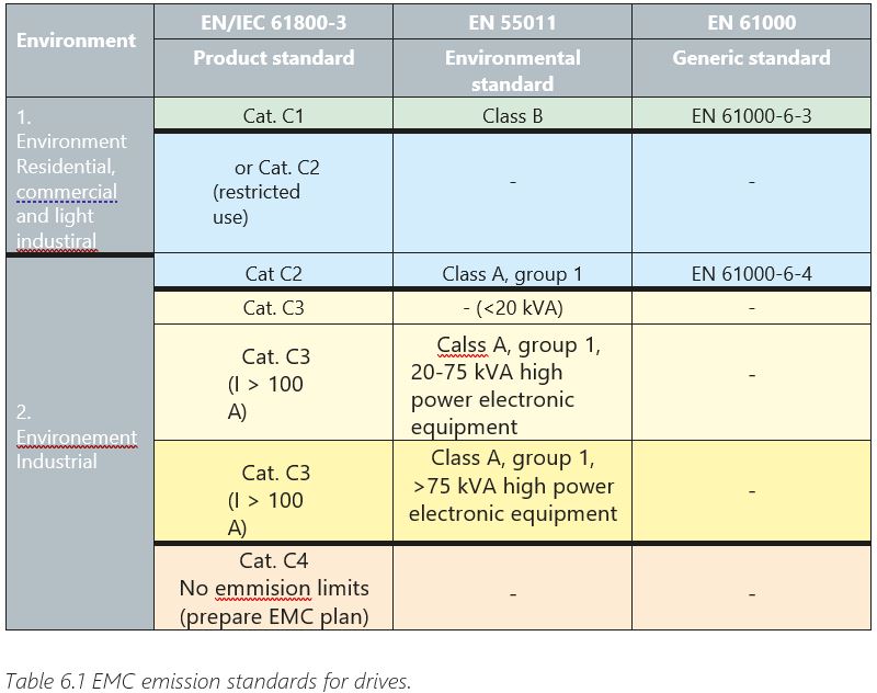
- – Basic standards deal with general aspects such as test set-up, measurement technique and emission lines. For adjustable speed drives the emission limits specified in EN55011 are commonly used
- – Generic standards deal with specific environments and have been mainly developed to fill in the lack of specific product standards. For residential, commercial and light industry environments the generic immunity standard is EN61000-6-1 and the generic emission standard is EN61000-6-3. For industrial environments the generic immunity standard is EN61000-6-2 and the generic emission standard is EN61000-6-4
- – Product standards apply for a specific product family. For AC drives the standard is EN/ IEC61800-3
The product standard for AC drives sets both immunity and emission limits depending on the environment where the drive is used: residential environment (more strict emission limits, not so high immunity levels) or industrial environment (less strict emission limits, higher immunity levels).