Yaskawa: Drive Retrofit Improves Efficiency for Water Treatment Plant
Application Overview
A Massachusetts-based municipal water treatment facility needed to upgrade their aging 350HP 18-pulse drives. They turned to a local Yaskawa drives distributor, who recommended a reliable, compact, and cost effective retrofit with Yaskawa’s U1000 Industrial Matrix Drive.
Challenge
The water treatment facility has four 350 HP pumps. The pumps run 25 MGD on average, but can reach 75 MGD in less than an hour with heavy rain fall. Three of these pumps can satisfy this peak demand. The last pump is used as back-up in case one of the three were to fail. Failure of one pump during peak flow without a back-up could lead to a precarious situation. If the back-up pump and the designated lag pump were to fail, the back-up of the influent main could cause overflowing manholes and flooded streets.
Based on the recommendations of the facility manager, the city made the decision to move forward with updating all of the influent drives. They began by upgrading their aging 350 HP Robicon 18-pulse pump drives, which had become time-consuming and costly to keep in working order.
Solution
 The Yaskawa distributor realized that a complete replacement would likely require a different size cabinet. The staff at the facility would also need time to become familiar with it. So they recommended a retrofit option using the Yaskawa U1000 Industrial Matrix drive.
After the facility contacted a sister facility which was already using Yaskawa drives, they agreed with the retrofit option.
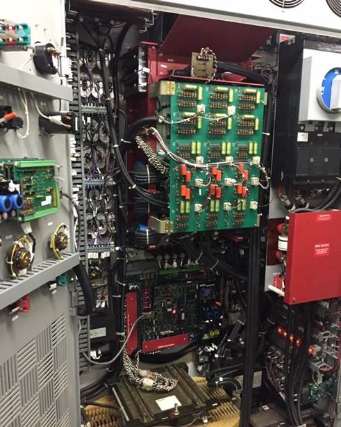
Since the U1000 drive is a stand-alone, low harmonic drive with regenerative capability, a lot of unnecessary components inside the cabinet were able to be eliminated. The circuit breaker from the previous system was also able to be reused.
Results
The U1000 solution meets the input harmonic current capabilities of the previous 18-pulse package at rated power and also provides excellent harmonic current levels throughout the load range.
The efficiency improvement was so dramatic that the water treatment facility was able to shut off the additional cabinet fans required to cool the previous system. They realized an immediate increase in efficiency due to reduction of the building’s cooling requirements.
Reusing the existing cabinet saved space, but also meant that virtually nothing had changed for the staff. All the old controls on the door were easily integrated into the U1000.
The Yaskawa solution provided all of these benefits at a cost of approximately half of a new 18-pulse configuration. As a result of this project, the water treatment facility has moved forward with updating several more of their outdated 18-pulse drives with the U1000.
How Do Matrix Drives Work?
Matrix drive design removes the DC bus by using nine bi-directional IGBTs in a matrix arrangement to generate the variable frequency AC output directly from the AC input. This dramatically reduces the effects of harmonic distortion on the output signal, producing a smoother, cleaner output waveform. With no DC bus to charge, the associated non-linear
input current draw can be eliminated, providing cleaner power to the load. Figure 1 shows the Matrix topology.
Note that in the Matrix design, any input phase can be connected directly to any output phase at any time. The key to the Matrix operation is its ability to turn on and off the bi-directional switches at the correct times to generate the proper output voltage and frequency required to operate the motor.
To better understand, let’s look at the three input phase voltages, shown in Figure 2.
In operation, the control built into the Matrix VFD continually monitors the voltage difference between each of the phases.
All drives use a PWM (pulse width modulation) waveform to generate motor voltage, including the Matrix drive. A standard drive pulses the DC bus to the motor to create the output voltage waveform. The time each pulse is ON (the pulse’s width) helps to determine the output voltage and final RMS voltage of each cycle of voltage.
Instead of using a DC bus, the Matrix drive pulses the motor using its input voltage. This is done in two steps. The low input voltage and mid input voltage is used for the first step and the mid-voltage and high voltage is used for the second step. The reverse order is used to turn off the pulse. This process is repeated over and over to generate the PWM output waveform constantly adjusted along with the ever changing three phase input voltage.
The constant use of the input voltage means current is constantly being drawn. Therefore, the Matrix drive does not mitigate harmonics. Instead, it naturally draws input current with less than 5% iTHD automatically as it provides motor control.
 Matrix Drive Regeneration
In addition to the low harmonics and near-unity power factor, the Matrix design also provides energy savings through regeneration. When a motor is being driven by a load, as opposed to driving the load, it acts as a generator, sending the extra power back to the VFD. The extra regenerative energy is then put pack onto the grid to be dispersed to other loads on the grid, which reduces the utility power demand. Examples include applications such as pump jacks, where the load oscillates between motoring and regeneration, and downhill conveyors that are in a continuous regenerative state.
In conventional drives, dynamic braking resistors can be used to divert the regenerative energy away from the VFD and prevent a DC bus overvoltage condition. The nine bi-directional IGBTs of the Matrix drive enable the regenerative energy to be directed back to the supply to be credited against the user’s power bill.
Monitoring
Some Matrix VFDs can monitor power in several ways to give instant feedback on energy saved. When provided with the $/kwh billing rate, the display on the drive can show the following information on request:
- Power output
- Power consumption
- Regenerative power
- Power saved
- Power bill
Comparison to Other Solutions
Of course, there are other means to mitigate the harmonics of VFDs. These include active front ends and multi-pulse transformers, which require significant additional components in combination with the VFD, all
of which mean added bulk, cost, and wiring connections. The Matrix accomplishes low harmonics all within the drive – three wires in, three wires out.