Motor Operation & Technical Review
June 2, 2021
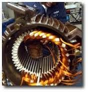
Motor Winding + Insulation Components
Everyday terms come into use in the electrical industry, one of which is ‘motor winding’. But what exactly are motor windings, what goes into them and what are their differences?
Here is a look at the various components that make up a motor winding and their importance to design, application and longevity of the motor.
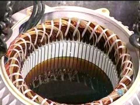
Coil / Winding
When one thinks of a what a motor winding is, the intuitive answer is the copper alloy coils that make up the actual current carrying component of the motor. Let’s start there. The metal making up the wire is generally copper (Element #29 in the periodic table of the elements). Copper has many free electrons in its outer shell (VSEPR theory) and is a relatively common element. Therefore, copper is cost effective when used as a conductor. In fact, the metallurgical makeup of the winding is actually a copper alloy; the alloy being less costly than pure copper without giving up significant performance attributes.
The ‘copper’ wire that makes up the winding is manufactured with a thin coat of varnish applied as an insulator so that adjacent strands of wire may physically be in contact with each other whilst each is still isolated from its neighbour. Together these strands make up a ‘coil’. There are different types of varnish that may be applied. The best currently available is rated for VFD service, and can be identified by the burn test.
Burning a wire intended for Non-VFD rated service will result in a black residue, whereas burning a wire that is designed for VFD rated service will yield a green residue (the green tinge comes from a trace amount of titanium in the varnish recipe). Theoretically, there should be no pinholes in the varnish coating of the wire strands.
In practice however, these are unavoidable and various electrical specifications will generally limit the number of pinholes per linear foot of wire. Thickness of the varnish is critical to the ultimate performance of the motor; it must be thick enough to prevent turn to turn shorts yet thin enough so as not to impede performance.
Stator Core
In the stator core (a stacked pile of laminations made from silicone electrical steel) the first step is to insert a ‘slot liner’ into each of the long hollow slots formed in the punch press on each lamination of electrical steel. In LVM this is usually a ‘Mylar NOMEX Mylar ‘sandwich in the shape of a long ‘U’. It is long enough to run the length of the stator stack plus a bit extra for a ‘cuff’ at either end.
The Mylar provides mechanical strength and shape, the NOMEX sets the temperature rating at 180°C (Class H).
The cuff adds mechanical strength as the coil exits the slot and needs that extra strength to resist grounding at the core edge.
After insertion of the slot liner, the first set of coils lays on the bottom of the slot, a centre stick is placed over that group and a second group of coils lays on top of the centre stick. A top stick seals the cavity and the process is repeated around the circumference of the motor core. To separate phases outside the core properly, a phase separator is used (Nomex).
The purpose of adding all these components is to isolate each strand, each coil, and each phase.
As the coil insertion is completed, the next step is to use a lacing material to tie the structure into place, while making certain that the coils are positioned and flared correctly, as not to touch the frame or bearing brackets. The lacing material is usually a heat-shrink product which becomes even tighter as the motor is baked in the oven to cure the non-hydroscopic varnish.
The idea after 2-3 varnish applications and bakes, is to solidify the windings into a solid mass and to displace any moisture or air gaps in the winding properly. As a variation on the theme, the lacing is tied in a more intense pattern on VFD rated motors, interconnecting as many coils as practical and creating a distinct ‘diamond’ pattern on the lacing.
The final step in the wind shop for most LVM is the ‘dip and bake’ process where the LVM core + coil + frame assembly is dipped into a non-hygroscopic varnish and cured in a temperature controlled oven, a process which may be repeated depending on frame size (volume) and manufacturer.
When the motor core emerges from the oven in the last round, the combination of the materials, the lacing and the varnish make for a very solid mass. The VFD rated motor with it’s intense lacing may ‘sing’ in service, the windings flexing and vibrating at the speed of sound at the core edge, the lacing and varnish working to hold it all in place as it wants to move.
‘Singing‘ in motor technology is not a good thing; a shortened life is the result as many non-VFD rated motors shall attest when applied on a VFD controlled system. There are many variations on the general theme, the nuances may be or may not be critical to use and will vary in importance by application. One of the most crucial aspects is the use of VFD control. In any event, the purpose here is to offer a basic understanding of the components and materials. For a further explanation, please feel free to consult your trusted source.