Facts Worth Knowing about AC Drives – Star and Delta Configuration in Field Weakening Operation Sections 4.5 – 4.8
August 13, 2020
4.5 Dynamic Brake Operation
Machines can create potential or kinetic energy which we want to remove from the machine.
- – Potential energy is caused by gravity, for example when a load is hoisted to a position and is being held in position.
- – Kinetic energy is caused by movement, for example a centrifuge running at a given speed which we want to reduce or a trolley to be
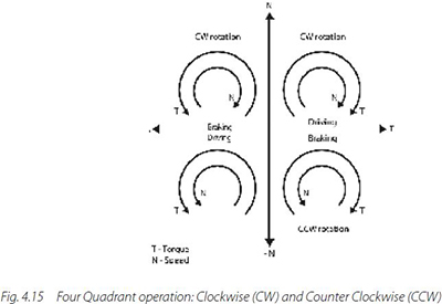
The dynamic characteristics of some loads require 4-quadrant operation. A reduction in the stator frequency (and voltage) by the AC drive allows the motor to act as a generator and convert mechanical energy into electrical energy.
Motors connected directly to the mains deliver the braking energy straight back to the mains.
If a motor is controlled by an AC drive, the braking energy is stored in the intermediate circuit of the drive. If the braking energy exceeds the power loss of the AC drive, the voltage in the intermediate circuit increases dramatically (in some cases exceeding 1000 V DC).
If the voltage exceeds the internal voltage limit, the AC drive is then switched off for self- protection and usually issues an alarm message or error code “over voltage”. Measures must be taken to prevent the AC drive being tripped if the motor feeds back excessive braking energy.
The following measures are typically used:
- – Extend the deceleration ramp time
- – Dissipate the energy in the motor. That is, the motor is used as a braking resistor
- – The AC drive is fitted with a “brake chopper” electronic circuit and appropriate braking resistors
- – Use of a regenerative braking unit to feed energy back to mains
- – Use of AC drives with an active rectifier to feed energy back to mains
- – The energy is fed to other drives through a common DC bus
- – The energy is fed to an energy storage (e.g. battery)
The first two measures require no additional hardware components. All the other measures do require additional components and must be considered at the design stage of the machinery.
4.5.1 Extending Deceleration Ramp
The deceleration ramp time can be extended by the operator by changing the relevant parameter setting. However, the operator must judge the load ratios himself.
Example
An attempt to brake a 22 kW motor operated by an AC drive from 50 Hz to 10 Hz within one second will end up with the drive tripping because the motor, acting as a generator, will feed back too much energy. The user can prevent the drive from tripping by changing the ramp- down time (for example, to 10 seconds).
Alternatively, the modern AC drive has control functions such as overvoltage control (OVC) that must be enabled to prevent the drive tripping or to automatically extend the ramps. The AC drive itself determines then the appropriate ramp time. This type of ramp extension automatically takes account of varying load inertias. Care must be taken when this kind of function is used on machines with vertical or horizontal movement (such as hoists, lifts, and portal cranes) as extending the ramp time does also mean that the traveling distance will be prolonged.
4.5.2 Motor as a Braking Resistor
Manufacturers use various methods for using the motor as a braking resistor. The basic principle is based on re-magnetizing the motor. Every manufacturer gives its method a different name, such as AC brake, flux brake, or compound braking. This type of braking is not recommended for highly dynamic applications (such as hoists or lifts) because the more frequent the braking, the hotter the motor becomes and consequently it can fail to perform as expected.
4.5.3 Brake Chopper Circuit (Brake Module) and Resistor
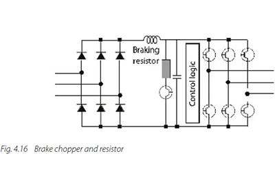
AC drives can be fitted with a brake chopper and a brake resistor. The circuit essentially consists of a transistor (for example, IGBT) that eliminates the excess voltage by “chopping” it and sending it to the connected resistor. The control circuit must be fed with the appropriate information during commissioning that a braking resistor is connected. The control circuit can also check whether the resistor is still in working order. Typically, it must be specified if an AC drive is equipped with a brake chopper or not, at the point of ordering.
Above a certain power level, the use of a braking module and resistor will cause heat, space and weight problems.
4.5.4 Use of a Regenerative Braking Unit
If the load often generates a great deal of regenerative energy, it may be useful to use a fully- regenerative braking unit.
If the voltage in the intermediate circuit rises to a given level, the DC voltage in the circuit is fed back to the mains, synchronously in both amplitude and phase, by an inverter.
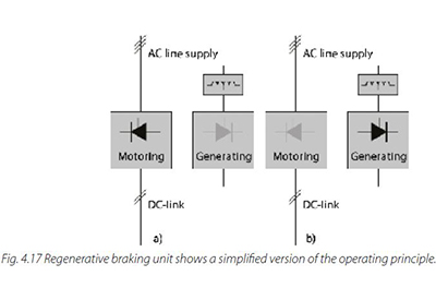
This feedback of energy can be accomplished by:
- – AC drives with an active rectifier. In this drive type, the rectifier can transmit energy from the intermediate DC circuit to the power supply
- – External regenerative braking units integrally connected to the intermediate circuit of one or more AC drives, monitor the voltage in the intermediate
For evaluation when it makes economic sense to use these kinds of devices please refer to chapter 5 Saving Energy with AC drives.
4.6 Static Brake Operation
The AC drive has several functionalities for locking or coasting the motor shaft, such as:
- – Coasting to stop
- – DC brake
- – DC hold
- – Electromechanical brake
The last three of these functions can typically only be performed after a stop command has been issued. This is often misunderstood in practice. It is important to note that a reference value of 0 Hz does not function as a stop command.
In general, do not use these functions when the direction of rotation is reversed.
4.6.1 Coasting to Stop
With the motor coasting, the voltage and frequency are immediately interrupted (0 V/0 Hz) and the motor is “released”. As the motor is no longer energized, it will typically spin down to zero speed. Depending on the speed and inertia of the load this can take from seconds to hours (for example, for huge separators).
4.6.2 DC Braking
A DC voltage across any two of the three motor phases is used to generate a stationary magnetic field in the stator. This field cannot generate high braking torque at the rated frequency. The braking power remains in the motor and may cause overheating.
Three parameters are required for DC braking:
- The frequency at which the brake should be activated. A frequency value below 10 Hz is recommended. Use the motor slip frequency as a guide. A frequency of 0 Hz means that the function is disabled
- The braking current used for holding the motor shaft. The recommendation is not to exceed the rated current of the motor in order to prevent possible thermal overload
- The duration of DC braking. This setting depends on the application
4.6.3 DC Hold
Unlike the DC brake, the DC hold has no time limit. Otherwise the above recommendations for the DC brake apply. This function can also be used when “auxiliary heating” is implemented for a motor placed in a very cold environment. As constant current flows through the motor, do not exceed the rated motor current. This minimizes the thermal load on the motor.
4.6.4 Electromechanical Brake
The electromechanical brake is an aid for bringing the motor shaft to a standstill. This can be controlled from the AC drive by means of a relay and there are various possible control options.
It is important to establish when the brake can be released, as well as hold the motor shaft. Some of the points to consider are:
- Motor pre-magnetization, meaning a minimum amount of current is needed
- The frequency at which activation or deactivation occur
- Reaction times (delay times) of the relay inductors
For critical applications such as hoists or lifts, once the start command has been given the brake may only be released after ensuring optimum pre-magnetization of the motor; otherwise the load could fall. A minimum current, usually the magnetizing current, should flow first to ensure that the motor cannot drop the load. For more information refer to chapter 4.10.
4.7 Motor Heating and Thermal Monitoring
Energy lost in motors during operation will warm up the motor. If the motor is heavily loaded, some cooling is needed. Depending on the system, motors can be cooled in different ways:
- Self-ventilation
- Forced air cooling
- Liquid cooling
To maintain the motor lifetime, keep the motor within the specified temperature range. The most common cooling method is self-ventilation, where the motor is cooled by a fan mounted on the shaft.
The temperature conditions of the motor are subject to two influences:
- When the speed decreases, the cooling air volume also
- When a non-sinusoidal motor current is present, more heat is generated in the
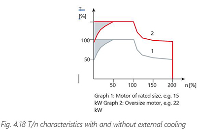
At low speeds the motor fan is not able to supply enough air for cooling. This problem arises when the load torque is constant throughout the control range. This lower ventilation determines the permissible level of torque during continuous loading.
When the motor runs continuously at 100% rated torque, at a speed which is less than half the rated speed, the motor requires extra air for cooling. This extra air cooling is indicated by the shaded areas in Fig. 4.18 T/n characteristics with and without external cooling.
Alternatively, instead of providing extra cooling, it is possible to reduce the motor load ratio. To reduce the motor load ratio, select a larger motor. However, the AC drive specification imposes limits on the size of motor that can be connected.
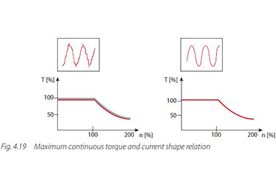
When the motor current is non-sinusoidal, the motor receives harmonic currents that increase the motor temperature, as shown in Fig. 4.19 Maximum continuous torque and current shape relation. The magnitude of the harmonic currents determines the amount of heat increase.
Therefore, it is advised to check the temperature rise class of the motor before operating it continuously at 100% load when the current is non-sinusoidal.
When the application predominantly requires low speeds, an additional fan to cool the motor is recommended to ensure full torque. However, the fan should be powered from a separate supply and should not be connected to the output of the AC drive. As an alternative to air, liquid can be used for cooling the motor. Liquid cooling is typically implemented in special motor designs.
Two temperature monitoring methods are implemented in the AC drive, in order to protect the motor:
Calculation:
The motor temperature is calculated based on a mathematical motor model.
Measurement:
Thermistors or PTCs placed inside the motor can be connected to the drive to monitor temperature
If motor overheating occurs, the remedial action required is programmed to fit the application needs.
4.8 Functional Safety
Machinery must be safe to operate. It is the responsibility of the machine builder to try to eliminate all risks by careful and efficient design. However, there is no such thing as totally risk-free machinery. Functional safety defines protection against hazards caused by incorrect functioning of components or systems. An AC drive is not a safety system as such, but it can be used as a part of a safety system. The role of a drive in a safety system is to be an actuator. It contains functions that can be certified for use in safety related systems or applications.
In Europe, functional safety falls under the Machinery Directive 2006/42/EC. The Machinery Directive describes the purpose of functional safety as follows: “Machinery must be designed and constructed so that it is fitted for its function, and can be operated, adjusted and maintained without putting persons at risk when these operations are carried out under the conditions foreseen but also taking into account any reasonably foreseeable misuse thereof.”
Depending on which application standard must be fulfilled, the system must reach a defined safety level. The required safety level is defined through a risk analysis. The risk analysis consists of finding out how severe accidents could happen, what is the likelihood that they could happen and how often the risk situations occur. The Machinery Directive refers to different standards, according to the safety level required.
In addition to the required safety level, it is important to recognize the type of the risk, and thus the required safety function. To be able to define this, it is necessary to understand how the machine behaves, what sort of a process it is used in, and what is the safest way, for example, to stop the machine if a risk has actualized.
The European functional safety regulations are comparable to many others around the globe. For example, in North America the OSHA (Occupational Safety and Health Act) applies, and in Canada the CCOHS (Canadian Centre for Occupational Health and Safety) provide the framework for applying safety measures. Although the relevant standards differ between the various regions, the safety principles are closely related. In general, it is common to use abbreviations in the different legislative frameworks and the standards to describe the safety function and the safety level.
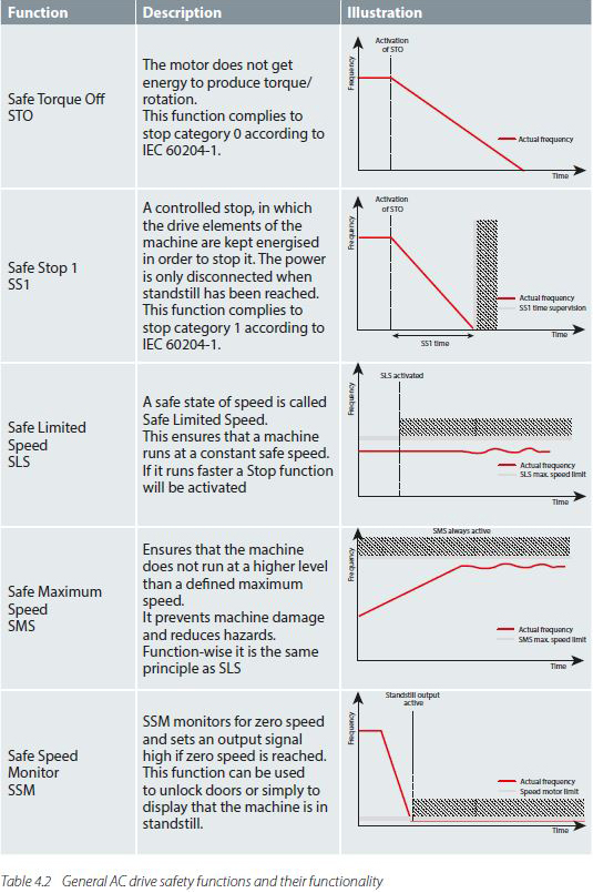
The product standard EN/IEC 61800-5-2 defines several additional functional safety functions for AC drives:
- – SOS Safe Operating Stop
- – SS2 Safe Stop 2
- – SDI Safe Direction
- – SBC Safe Brake Control
- – SMA Safely-Monitored Acceleration
- – SLP Safely-Limited Position
- – SCA Safe Cam
- – SLI Safely-Limited Increment
- – SSR Safe Speed Range
- – SBT Safe Break Test
- – SQS Safe Quick Stop
- – SLA Safely-Limited Acceleration
- – SAR Safe Acceleration Range
- – SLT Safely-Limited Torque
- – STR Safe Torque Range
- – SMT Safe Motor Temperature
SISTEMA
Independent Software tools such as SISTEMA (Safety Integrity Software Tool for the Evaluation of Machine Applications) help the machine builder to make all the calculations of the safety application.
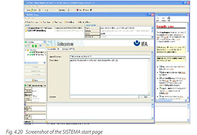
The SISTEMA software utility provides support to developers and testers of safety-related machine controls, in evaluation of safety in the context of ISO 13849-1. The tool enables modelling of the structure of the safety-related control components based upon the designated architectures. This modelling enables automated calculation of the reliability values with various levels of detail, including that of the attained Performance Level (PL).
Relevant parameters are entered step-by-step in input dialogs, for example:
- – risk parameters for determining the required performance level (PLr)
- – the category of the SRP/CS
- – measures against common-cause failures (CCF) on multi-channel systems
- – average component quality (MTTFd)
- – average test quality (DCavg) of components and blocks
The impact of each parameter change upon the entire system is reflected immediately in the user interface. The final results are printable in a summary document.