Facts Worth Knowing About AC Drives – Electric Motors Sections 2.4 – 2.4.8
May 19, 2020
2.4 Synchronous Motors
The synchronous motor is defined by the fact that the rotor rotates at the same speed as the magnetic field created by the stator windings. The design of the stator is in many cases similar to that of induction motors, with distributed windings. Some manufacturers use concentric windings (in slot) which enable a more compact motor design and require less copper. The energy savings achieved by the reduced use of copper are however often eaten up by additional losses, which result from harmonics in the air gap flux caused by the construction.
The torque produced by a synchronous motor has two different sources. One is the interaction between the rotor flux and the permanent magnet torque, the another is the design asymmetry/anisotropy in the motor (saliency torque). An overview of the motor types may be provided by considering two indicators: Saliency, which expresses the effect of the asymmetry in the motor (anisotropy) on the inductances and is defined by the ratio of the highest to the lowest inductance.Tpm/Ttotal, which expresses the contribution of the permanent magnet torque to the total torque.
The main synchronous motors types (Surface mounted magnets SPM, Interior mounted magnets IPM, Synchronous reluctance motor SynRM and permanent magnet assisted Synchronous reluctance motor PMaSynRM) are generic located with respect to saliency and to permanent magnet contribution to the total torque, Tpm/Ttotal, as illustrated:

• In SPM the amount of magnet is high, and the entire torque production is due to the rotor permanent magnet flux, thus Tpm/Ttotal ≈ 1. The anisotropy is low, thus saliency ≈ 1.
• In SynRM there is no magnet in the rotor, thus Tpm/Ttotal = 0 and the entire torque production is due to the reluctance torque. The anisotropy is high and so saliency is.
• Between SPM and SynRM any combination is theoretically possible. The IPM are generally achieved by design as illustrated and Tpm/Ttotal >0.5 (pm torque dominates). The PMaSynRM are generally achieved by designs as illustrated and Tpm/Ttotal <0.5 (reluctance torque dominates). However, for control is not important to distinguished between IPM and PMaSynRM.
2.4.1 Permanent Magnet (PM) Motors
The simplest way to build a permanent magnet motor (PM motor) is to replace the squirrel-cage rotor of an induction motor with a rotor which is equipped with permanent magnets. When applying a suitable voltage to the stator, a rotating magnetic field will be created in the air gap.The rotor will follow the field at synchronous speed because the magnets are attracted by the rotating field. If the difference between rotor speed and the speed of the magnetic field is too big the motor falls out of synchronicity and the motor will stop. Therefore, a suitable controller is required which ensures that speed changes are done by adjusting the feeding frequency continuously and not by switching from one speed to another.
In the past PM motors were often used in servo applications with focus on fast and precise operation. These servo motors are typically slim and long in order to have a low inertia for high dynamic applications. To utilize the high-efficiency characteristic of PM motors in other applications the principle has been transferred to motors in IEC frame sizes. Standard AC drives can be used in the majority of PM motor systems for operation if suitable control algorithms are implemented in the device.
To magnetize the motor in the best way the controller needs to know the rotor angle at any point in time. In many applications sensorless strategies for determining the rotor angle are sufficient. For example, see chapter 3.7.6 Integrated Motion Controller. If the controller is not capable of sensorless control or in high dynamic servo applications, external position feedback devices are used.
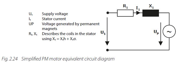
In the equivalent diagram the magnets are represented by a voltage source Up because turning the rotor will result in a voltage induced in the stator. This voltage is called back EMF, see section 2.4.1.1 Back EMF. The absence of motor slip, rotor resistance and inductance indicate that no losses are created in the rotor, which results in the very good efficiency.
ln general PM motors can be divided into motors with rotors where the magnets are placed on the surface (SPM motor) or internally (IPM motor). The placement of the magnet results in different shapes of the resulting magnetic field and is described by the inductances Ld and Lq.
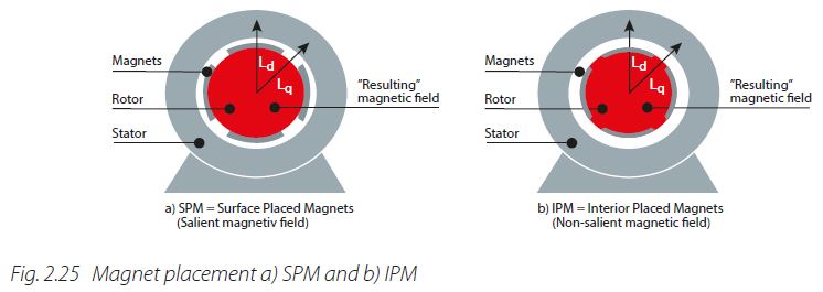
As the magnets behave like air in relation to the resulting magnetic field, salient and non-salient fields are created. With SPM motors Ld and Lq have the same value resulting in a non-salient field while the different Ld and Lq of an IPM creates a salient field which produces an additional torque in field-weakening (see chapter 4.1.1).
2.4.1.1 Back EMF
When the shaft of a PM motor is turned, the motor produces a voltage at its terminals. This voltage is called back EMF (EMF = electromotive force) and describes an important characteristic of the motor. The higher the voltage, the better the motor efficiency. Depending on the connection and placement of the windings, the shape of the back EMF can be trapezoidal or sinusoidal. For trapezoidal voltage so-called block commutation is required which is easy to realize in the electronics but has drawbacks like noise and torque ripples. Typically, PM motors have sinusoidal back EMF and will be operated via sinusoidal commutation.
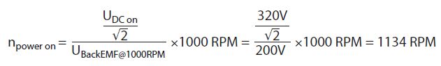
Given that the motor actively generates a voltage must be considered, not only during operation but also when the feeding AC drive is disconnected from mains (power loss, break down, switched off ). The motor can potentially generate sufficient energy to power up the device while the shaft is rotating (for example, when coasting). The voltage needed for powering the drive depends on the mains voltage the drive is designed for.
Example: Required speed of a PM motor with 200Vrms back EMF to power on a 400 V mains AC drive (required DC-link voltage approx. 320 V).
If the voltage generated by the motor is too high the drive can be destroyed. Practically this can happen when the controlling drive is switched off while the motor is operating at very high speed. During operation the drive limits the voltage coming back from the motor. When the control is suddenly switched off the full back EMF voltage can be seen at the terminals immediately. This critical speed depends on the back EMF of the motor and the voltage the drive is designed for.
Example: 400 V mains, UBack EMF @ 1000 RPM = 100Vrms, UDC critical = 1000 V

A brake resistor can be used to overcome such critical situations.
Unfortunately, there is no standard used by motor manufacturers to provide information about the back EMF. Some manufacturers state back EMF related to 1000 RPM while others use nominal speed of the motor.
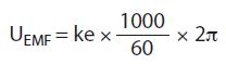
Sometimes the value of factor ke is given in radians and must be converted to RPM. Where peak values are provided the voltage must be divided by square root of two to get the RMS value.
Also, advanced motor data like motor resistance and inductances are stated in differing ways. Sometimes they are given as phase/phase values, and sometimes as phase/star values.
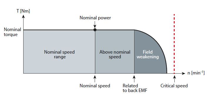
2.4.1.2 Torque and Speed Range
The torque of a PM motor is proportional to the motor current, and its speed is proportional to the feeding frequency. At nominal torque and speed, a certain voltage is required. If the AC drive can deliver a higher voltage, the speed can be increased further. This results in a higher power at constant torque. When the voltage has reached an upper limit, the motor enters the field weakening area. Operation in field weakening is only possible with suitable AC drives. Motor mechanics and insulation must support the higher speed and withstand the higher voltage.
The greatest risk in field weakening operation is switching off the motor control at too highspeed, as the high back EMF can destroy the AC drive (see section 2.4.1.1 Back EMF).
Another possibility for extending the speed range is to change the star configuration of a motorto delta, if the motor provides this feature. Similar to induction motors, a delta connection resultsin a higher voltage on the windings, because it is not reduced by the factor 1.73√3 as for a starconfiguration.
2.4.2. Brushless DC (BLDC) or Electronically Commutated (EC) Motors
EC (Electronically Commutated Motor) and BLDC (Brushless DC) are basically different names for the same technology. In the original BLDC concept only two phases were energized with a trapezoidal voltage. Compared to a distribution over three phases this result in 1.22-time higher current. For determining the rotor position Hall sensors have been used. Drawbacks of the concept were worse torque ripples and iron losses.
In practice there are many different types of EC motors, such as small servo motors with power ratings of a few watts or motors in building automation systems up to approximately 10 kW. In general BLDC/EC has a reputation for extremely high efficiency. This is fully deserved, in particular for very small devices – the original application area for these motors – where they are distinctly better than universal or split-pole motors (efficiency approximately 30%). Above a few hundred watts the efficiency is comparable to standard PM motors.
Modern EC/ECM utilize the same control principles as the PM motors. In building automation EC motors are often used as hubs in EC fans. This results in a very compact fan unit with a very efficient motor. Unfortunately, the placement of the motor in the middle of a centrifugal fan creates air turbulences which reduce the total fan efficiency. In comparison to the Danfoss EC+ solution, which allows highly efficient PM motors to be used with Danfoss VLT drives, the difference in total system efficiency can be in the range of 5-7%.
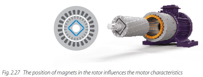
2.4.3 Line Start PM Motor (LSPM motor)
A line start PM motor is a hybrid of a squirrel-cage induction motor and a PM motor where the magnets are placed internally to the rotor.
When connected to a three-phase grid the motor develops a torque and accelerates like a standard induction motor to near synchronous speed if the motor torque is greater than the load torque throughout acceleration. When the rotor has roughly reached the speed of the rotating field, a synchronizing torque (reaction torque) is produced due to magnetic coupling between the rotating stator field and the rotor poles, which pulls the rotor into synchronism.
After synchronization, the motor continues to run at synchronous speed. As there is no speed difference between the magnetic field and the rotor, no currents are induced in the cage. This results in a high efficiency with a good power factor. When load changes take place the squirrel cage is still working as a damper. This is also the case when the motor is operated by an AC drive where the additional damper can reduce the efficiency by approximately 5-10%.
If the motor is loaded with a torque that is greater than its synchronous stalling torque, it is pulled out of synchronism and continues to operate like an induction motor at a load-dependent speed. Depending on the design, the motor is more or less sensitive to undervoltage situations which can also result in falling out of synchronism. Renewed synchronization takes place automatically when the load torque is lower than the synchronizing torque. However, the rotor will stop if the motor is loaded with a torque that is greater than its induction stalling torque.
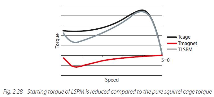
Drawbacks of the concept are the influence of the magnets while starting the motor. Torque oscillations and torque peaks, paired with noise, arise during the start up. Furthermore, the starting torque is lower compared to an induction motor as the magnets create a negative torque component.
LSPM motors are typically used in fans and pumps, available in the power range up toapproximately some 10 kW but can also be used in low inertia applications.
2.4.4 Reluctance Motors
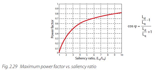
For creating a motor movement these types of motors utilize magnetic reluctance, which is also called magnetic resistance. Similar to electric circuits the magnetic flux follows the path of the lowest resistance. As in induction motors, the magnetic field is created by applying a suitable voltage to the stator windings. The rotor rotates towards the position with minimum magnetic reluctance. If the rotor is now forced out of this position a torque is created in order to move it back to the position where the reluctance is minimized. The torque resulting from the magnetomotive force depends on the relationship between the inductances in the d-axis and q-axis, known as the saliency ratio.
The saliency ratio results directly from the rotor lamination design. Cut-offs in the lamination are utilized to shape the equivalent air gap of the machine by controlling the flux paths. They also influence how the d-axis and q-axis inductances vary with the magnetization current. As these cut-offs increase the equivalent air gap, a higher magnetizing current is required which leads to a worse cos φ. As illustrated in Fig. 2.29 Maximum power factor vs. saliency ratio, the maximum power factor depends on Ld/Lq ratio. The higher the ratio the better the cos φ becomes. Modern rotor designs have a ratio in the range from 4 to 10.
Reaching power factors as high as induction motors is difficult for reluctance motors (requires a very high saliency ratio), but the energy efficiency is reasonably high. Losses arise in the rotor mainly by harmonics in the air gap between stator and rotor.
The reluctance principle was first used around the year 1840. Over time various optimizations resulted in different motor principles and designs. In the next chapters the three most common types of reluctance machines are described.
2.4.5 Synchronous Reluctance Motor with Squirrel Cage
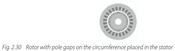
The stator of this three-phase reluctance motor is identical to that of a standard three-phase squirrel-cage motor. The rotor design is modified by removing the rotor bars and cutting pole gaps on the circumference of the laminated rotor core. The gaps are filled again with aluminum and the end windings are shorted.
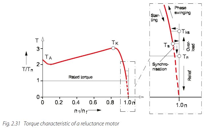
Similar to a LSPM motor design, (see section 2.4.3 Line Start PM Motor (LSPM Motor)) the motor accelerates to near synchronous speed when connected to a three-phase grid, if the produced torque is sufficient for the load. When approaching the synchronous speed, the rotor is pulled into synchronism and runs at synchronous speed despite the absence of rotor excitation.
Under load, the salient rotor poles lag behind the stator rotating field by the load angle. Again, the behavior is similar to LSPM when the load torque becomes too high. The motor is pulled out of synchronism, continues to operate like an induction motor and regains synchronization automatically when the load torque is lower than the synchronizing torque.
The possibility to start direct on line (DOL) and run at synchronous speed make the motor interesting for several applications. Power range ends often at approximately 10 kW. The drawback is a reduced efficiency, especially when operated by AC drives, as the rotor windings act as an additional damper.
2.4.6 Synchronous Reluctance Motor (SynRM)
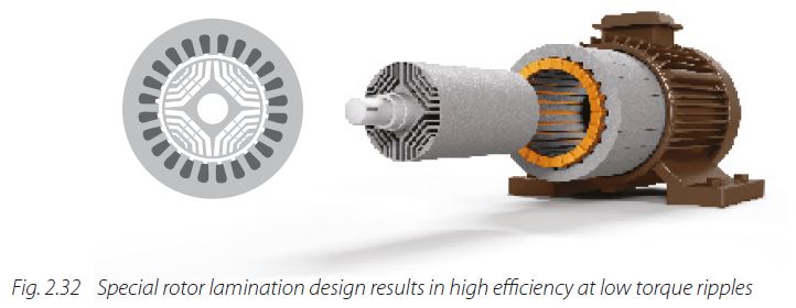
The design of a new generation of reluctance motors focuses on energy efficiency. This highly efficient motor type is often meant when synchronous reluctance motors are addressed and should not be confused with reluctance motors which focus on high torque density or the possibility to start on mains. The key to the efficiency is the new rotor design.
The stator construction and the windings are similar to an induction motor. By applying a suitable voltage to the distributed windings, a harmonic field is created which creates low harmonic losses. Also, the design of the rotor is optimized to reduce harmonic losses and operate with low torque ripples.
As the motor cannot start directly on mains, an AC drive is required to control the motor. For magnetizing the cut-offs in the rotor lamination, higher apparent power is required than for an induction motor (see section 2.4.4 Reluctance Motors). If the converter and the capacitors in the intermediate circuit are suitably sized, they will deliver the additional apparent current. In this case the grid is not loaded with the higher apparent power and the low cos φ.
For operating the motor, the AC drive needs to know the rotor angle. Depending on the angle, the drive will energize the different windings. The determination of the rotor angle is often done sensorless without an additional device. To achieve an energy efficient control, the converter must also take care of the Ld and Lq behavior in operation.
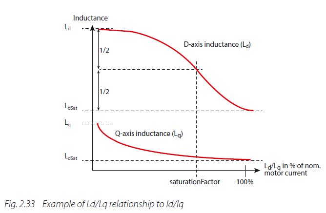
The inductance components of the SynRM rotor change depending on the load because of saturation effects. Therefore the individual inductances Ld and Lq depend on Id and Iq current (Ld(Id,Iq) and Lq(Id,Iq)). The inductances are determined automatically by the frequency converter at commissioning. If this is considered, very high energy efficiency operation of the motor is possible. Over a certain power range, the part-load efficiency has advantages against other concepts.
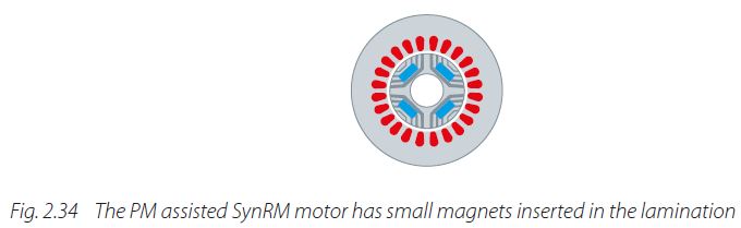
2.4.7 Permanent Magnet Assisted Synchronous Reluctance Motor (PMaSynRM)
The PMaSRM is built as a variation of SynRM, by adding weak magnets to the rotor geometry. Although, the location of the magnets may differ from design to design, their purpose is to saturate the rotor ribs, thus increasing the torque production and improving the power factor.
In contrast to SynRM, where the entire electromagnetic torque is produced by the differences in the reluctance around the rotor (reluctance torque), in the PMaSynRM, the electromagnetic torque is produced by reluctance torque and by interaction of the permanent magnet flux with the magnetizing stator current (pm torque). From the point of view of the control, the PMaSynRM is like an IPM. The difference between an IPM and a PMaSynRM consists in the fact that in an IPM the torque produced by the permanent magnet is higher than the reluctance torque, while in PMaSynRM the reluctance torque is dominant.
In practice are also motors, which are named IPM, but in the reality have properties similar to a PMaSynRM. The motor parameters required by control are as for IPM the line-to-line back emf at 1000rpm and the variation of Ld and Lq inductances with the current as described in Fig. 2.33.
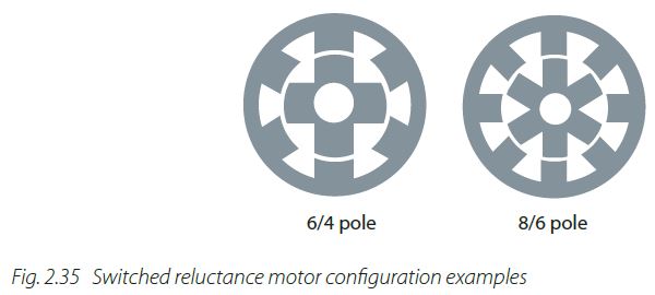
2.4.8 Switched Reluctance Motor (SRM)
Construction of the stator is very similar to that of DC motors as concentric windings are used. This can result in a compact housing. The rotor lamination design has a very clear shape with low inertia where the number of poles can easily be counted. While on two pole motors the rotor, poles are aligned with the stator poles, the pole ratio is typically different. This principle is also applied on other motor types, but it is obvious on switched reluctance motors.
To run the motor a suitable controller is required, which energizes the stator inductors in a sophisticated way. The phases are energized one after the other. When the inductors of a phase are supplied with a voltage, a flux is established through the stator poles and the rotor, which results in rotor movement. After the rotor has started moving the voltage will be switched to the next phase and so on.
Starting the motor directly on mains is not possible. The design allows 100% torque at stall indefinitely and achieves high efficiency even in part-load operation. The double salient construction in rotor and stator is very robust but results typically in high torque ripples and low dynamics at higher noise.
For decades, induction motors were state of the art, while other technologies were only used in niches. The trend towards more energy efficient motors and the opportunities provided by AC drives has resulted in innovative technologies like the improved SynRM. More improvements and optimizations are in development.
It is, also, important to mention that these kinds of motors do not run on AC drives.