Understanding Torque Ripple in Servo Motors

March 4, 2018
By: Warren Osak
Servo Mode of Operation
Before specifying torque ripple for a servo system, the mode of operation for the system should be determined: closed torque or closed velocity loop. If the servo system is used as a tensioning device (ie. film, web drives) it will be used in a torque control servo loop with no velocity feedback. In this application, inherent torque ripple components of the motor and those induced from the drive amplifier will be present. If the servo system is used as an axis feed servo (ie. grinder axis drives), it will be controlled in a closed velocity loop. In these applications the velocity loop bandwidth will determine how well the servo can compensate for its inherent torque ripple components. Data for a slotless motor design is presented for closed velocity loop servo mode.
Torque Ripple Specification
Torque ripple must be defined as a function of output load and speed. For load specification the most sensible rating point is the continuous duty thermal torque rating for the servo motor. At this point, the magnetic circuit of the motor is loaded sufficiently by the stator excitation which will bring out the worst case iron saturation effects within the continuous duty zone. Thus, a realistic picture of the torque ripple characteristics of the motor is obtained.
The speed at which torque ripple data is taken is determined by bandwidth of the servo system and frequencies of major components of torque ripple. The speed must be low enough such that system inertia does not damp out torque variations. Also, the speed should be high enough such that certain ripple frequencies are near the bandwidth of the system. A reasonable speed which meets these criteria and offers easy conversion of frequencies to cycles per motor revolution is 60 rpm. All test data presented is taken at this speed.

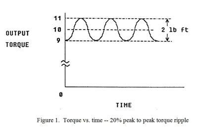
With the load and speed measurement points established, the final specification is how the magnitude of torque ripple will be rated. Figure 1 shows a hypothetical torque ripple output plotted vs. time. Torque ripple is specified as the peak-to-peak variation in torque output output expressed as a percentage of average output torque. Figure 1 shows a peak-to-peak torque variation of 2 lb. Ft. While delivering 10 lb. Ft. average (or dc) torque. The torque ripple is therefore, rated as 20% peak to peak, 10% average to peak.
In summary, torque or velocity loop servo mode of operation must first be determined. Tests can then be run at 60 rpm under the appropriate servo mode.
Torque Ripple
Typical torque ripple measurement hardware consists of a servo motor directly coupled to a torque transducer which in turn is directly coupled to a loading device. Various load methods have been used such as eddy current brakes and dc generators. However, few devices work as well at low speeds as a prony friction brake. The prony brake consists of a hollow drum, partially filled with cooling water, over which a friction belt rides. The tension of the belt determines the torque loading.
The torque is measured from the analog output of the torque transducer. This signal can be monitored as a function of time on an oscilloscope. However, a more revealing method is to monitor the individual frequency components of the torque output. Through the use of a frequency spectrum analyzer, the frequency components of torque (pole and slot ripple, etc.) can be identified and treated individually.
Torque ripple is not only difficult to measure, but it is also sometimes ambiguous to specify. Preferably, torque ripple tests should be run at application speeds and loads. However, these parameters are very often not available, and therefore, some common rating baseline against which systems can be compared must be established.

Warren Osak is Founder and CEO of Electromate