Exploring Permanently Mounted Voltage Testing Products
April 6, 2021
There are a variety of different electrical safety products that are permanently mounted, each with different functionality and limitations. They all have different purposes and should not be discussed interchangeably. Three common types of permanently mounted products are Voltage Indicators, Test Portals, and Absence of Voltage Testers.
Voltage Indicators – Detect Presence of Voltage
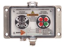
Voltage indicators are permanently mounted and use LED-style indicators that illuminate when presence of voltage is detected. They typically illuminate at approximately 40V to 1000V, depending on the device and manufacturer.These devices are an excellent way to provide a visual warning when voltage is present.
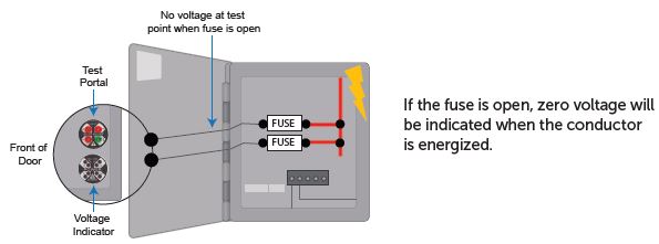
Voltage indicators should never be used to verify the absence of voltage. Equipment may be energized, even if the voltage indicator is not illuminated. Lack of illumination can be caused by a failed LED, a bad installation, or a failed device. Installation codes often require voltage indicators to be fused. If the fuse is open, the voltage indicator will not illuminate when voltage is present.
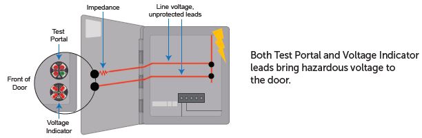
Additionally, voltage indicators bring line voltage (for example, 480V) directly to the door or external surface where the indicator is installed. This could present a shock hazard, especially when troubleshooting with the door open as door mounted devices typically operate at control voltages and workers may not be expecting the wires to the indicator to carry hazardous voltages. Wires that carry three-phase voltage across a hinge need to be protected to ensure that repeated opening and closing of doors does not pinch or damage the wire or insulation.
Regardless of whether electrical or mechanical work will be performed, voltage indicators are not a test instrument and should not be used when verifying the absence of voltage.
Test Portals – Measure the Presence of Voltage
Test portals are permanently mounted devices that can be used with a portable tester, such as a digital multimeter, to measure voltage.These devices are an excellent tool for troubleshooting and determining the magnitude or value of any voltage that is present. Test portals will test at the point in the circuit at which the test leads are installed. If there are multiple test points, more than one test portal may be required. Test portals may have features such as IP20 “finger safe”ingress protection as well as a high impedance circuit located at the door to limit current at the test points to less than 5mA. The impedance reduces the likelihood of shock or arc flash when measuring voltage presence via the portals, but the added impedance requires a conversion to determine the actual voltage value.
Should Test Portals be used to Verify Absence of Voltage?
The process for verifying the absence of voltage, often referred to as the “live-dead-live test,” is described in CSA Z462 4.2.5. Using test portals with a portable test instrument can lead to unreliable results when testing for absence of voltage and is not recommended. Here are some of the reasons why voltage test portals are not adequate for absence of voltage testing:
a) Installation test – verifying absence of voltage through a permanently mounted device requires assurance that you are in contact with the test point when the measurement is taken. If the leads from a permanently mounted device are not properly terminated or disconnected, voltage will not be detected, regardless of whether or not the conductor is energized. This is why permanently mounted voltage testers are required to have an installation test to confirm that the device is in contact with the conductor at the time the voltage measurement is taken.
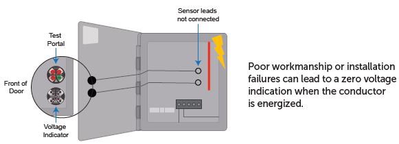
Test portals do not have a feature to verify leads are connected to the source conductor when a measurement with a portable test instrument is taken. This condition could result in reading zero voltage when voltage is present. Even if it is possible to use a portable tester to measure voltage presence through test portals before opening the disconnect, it does not guarantee that the test portal installation is valid after the disconnect is opened. A known voltage source is also required to verify the portable tester is functional after measuring through the portals, which may require PPE.
b) Installation code requirements – the local authority having jurisdiction (AHJ) will often require overcurrent protection for test portals with leads longer than 12 inches in order to meet NEC, CEC, or UL 508A requirements. If fusing is required, testing through the portals will only test the load side of the fuse, not the actual circuit part. The circuit part could be energized if the fuse is open and a portable tester would not detect voltage through the test portal. Use of fuses or terminal blocks to extend test portal leads to comply with installation codes introduces additional installation failure points.
c) Bringing hazardous voltage to the door – installing test portals requires routing wires that carry hazardous line voltage across the hinge and/or to the external enclosure. Bringing source voltage (ex. 480V) directly to an accessible surface is not a best practice, particularly when that surface moves, like a door. The wire will be subject to wear and tear and could eventually present shock hazards if not properly installed and maintained (another reason why the installation test described earlier is so critical). Test portals are designed with the impedance at the portal; therefore, the wire is not protected.
Test portals are a great tool to reduce risk when troubleshooting and measuring voltage presence. However, proving absence of voltage through a permanently mounted device has additional requirements.
The test portal can be thought of as an extension of the circuit part or source conductor – not the actual circuit part. Portals are okay to do a preliminary verification check at the portal. However, before removing PPE or performing any work, best practice is to perform an additional test with the portable test instrument directly at the source conductor or actual circuit part to conclusively prove a de-energized condition exists.
Absence of Voltage Testers – Verify Circuit is Deenergized
Absence of Voltage Testers (AVT) are permanently mounted test devices designed specifically to prove the absence of voltage exists. With AVTs, the absence of voltage is verified prior to opening an electrical enclosure. Requirements for AVTs are described in UL 1436. To operate an AVT, a user pushes a button to initiate the test sequence. The test sequence is performed automatically and includes verifying the tester is functioning with a known voltage source, ensuring the tester is properly installed and in direct contact with the circuit at the time of testing, and testing for absence of AC and DC voltage phase-to-phase and phase-to-ground. If all requirements in the test sequence are satisfied, a green indicator will illuminate to visually convey that the absence of voltage has been confirmed.
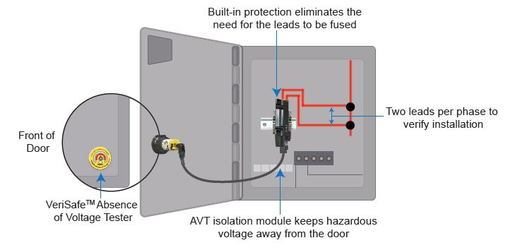
Requirements in UL 1436 for AVTs are very extensive and include avariety of features to ensure the absence of voltage test function is fail-safe and reliable. Active indicators, built-in overcurrent protection, and SIL 3 reliability for all safety functions are some of the important features. Built-in overcurrent protection ensures that the AVT can be installed directly in contact with the circuit being tested (without the need for in-line fusing) eliminating the failure modes that voltage indicators and test portals are subject to. In addition, AVTs are designed to keep hazardous voltage away from the door and user interface.
Like voltage indicators and test portals, AVTs will only test the point in the circuit at which the test leads are installed. If there are multiple test points or multiple sources of electrical energy (including stored energy sources) additional testers may be required.
AVT manufacturers often include voltage presence indicators as an additional feature, but this functionality is separate from the absence of voltage safety function and is not required by UL 1436.
Reliable Results with AVTs
Case Study: Ground Lead Failure
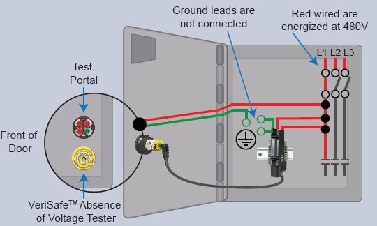
Situation
Worker approaches the enclosure and the disconnect switch for the 480V power source is in the OFF position. The disconnect switch has failed with one phase (L1) in the closed position (L2, L3 are open). The ground leads of the devices are NOT connected to ground because of an improper installation or termination failure.
The worker applies a lock. Following safety procedures, the worker performs an absence of voltage test with the electrical enclosure closed using a permanently mounted device.
Permanently Mounted Test Devices in Standards & Regulations
Best practice for verifying the absence of voltage is described in the CSA Z462. CSA Z462 has requirements for verifying the absence of voltage with portable test instruments (4.2.5(g)) and permanently mounted absence of voltage testers (4.2.5(g) Exception 2). Presently, the 2018 edition of Z462 states that permanently mounted absence of voltage testers can be used in conjunction with a portable test instrument. However, in the upcoming 2021 edition, CSA is expected to revise Z462 to allow Absence of Voltage Testers to be used to verify an electrically safe work condition in lieu of a portable test instrument.
(g) Use an adequately rated portable test instrument to test each phase conductor or circuit part to verify the absence of voltage. Test each phase conductor or circuit part both phase-to-phase and phase-to-ground. Before and after each test, determine that the test instrument is operating satisfactorily through verification on any known voltage source.
Exception 2): An adequately rated permanently mounted absence of voltage tester may be used to test for the absence of voltage of the conductors or circuit parts at the work location, provided it meets the following requirements:
- a. It is permanently mounted and installed in accordance with the manufacturer’s instructions and tests the conductors and circuit parts at the point of work
- b. It is listed and labeled for the purpose of verifying the absence of voltage
- c. It tests each phase conductor or circuit part both phase-to-phase and phase-to-ground
- d. The test device is verified as operating satisfactorily on any known voltage source before and after verifying the absence of voltage
Comparison of Devices and Capabilities