Comprehensive Guide to the CiA 402 Drive Profile
June 2, 2020
The CiA 402 application profile is used to standardize the control of VFDs and servo drives. A previous post provided an introduction to the profile. This post will go into more detail on how the profile functions and how it can be implemented.
CAN System
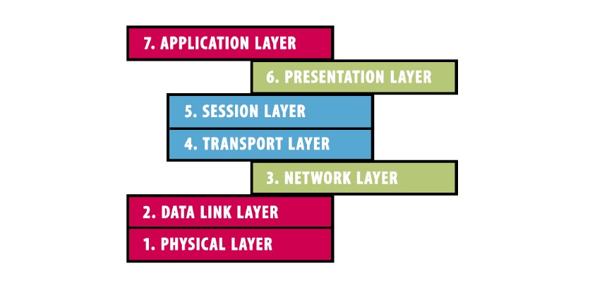
The Controller Area Network (CAN) system is built upon the ISO Open System Interconnection (OSI) seven-layer model. This model is designed for the interoperability in the communication of a computing system without defining how this goal is achieved through actual hardware or software. The model is made up of seven layers: physical, data link, network, transport, session, presentation, and application.
Each layer is served by the layer below it and serves the layer above it (e.g. the data link layer is served by the physical layer and serves the network layer). For CAN networks the physical and data link layers are considered lower layer protocols and the application layer is considered a higher layer protocol. Meanwhile the network, transport, session, and presentation layers are often not explicitly implemented.
Multiple higher layer protocols are supported by CAN systems. The simplest and most common is CANopen. This defines an addressing scheme, communication protocols, and, most importantly for this post, a device profile in the application layer. CAN in Automation (CiA) specifies CiA 301 as the basic device and communication profile. It is upon this base that more advanced application profiles are built. Examples include CiA 401 for I/O modules, CiA 417 for lift applications, but also the CiA 402 for VFDs and servo drives.
CiA 301 Profile
Before understanding how the CiA 402 profile functions, it is beneficial to first know what is defined by CiA 301. First, the communication is implemented and follows a state machine for starting and restarting devices. Then there is the object dictionary which defines all variables. The object dictionary is specified in an EDS file, which can be created for KEB drives using the Combivis 6 wizards. Ultimately the application is what actually achieves the profile function. The application is manipulated by the variables in the object dictionary and then data is read/write across the communication layer.
In the object dictionary each entry contains an index, object type, name, type, and attribute. First, the index is a 16 bit hexadecimal address and for CiA 301 range from 0x1000-0x1FFF. The object type simply defines whether the entry is an array, record, or simple variable. Next is the name, which is a string defining the entry such as vendor ID, control word, etc. Then the type defines the datatype of the variable (INT, USINT, BOOL, etc.). Finally the attribute provides whether the entry is read only, write only, or read/write.
CiA 402
Building upon the basics of CAN and CiA 301, the CiA 402 profile is meant to define the behavior of inverters and servo drives. It is based on finite state automation (FSA) which is a state machine with definitions for behavior at each state. The system must step incrementally through the state machine; it cannot jump over state(s) to get to a final state. The states can be changed due to internal events in the drive (terminal I/O, internal logic, etc.) or from Service Data Objects (SDO) and Process Data Objects (PDO).
PDO and SDO
PDO and SDO are the heart of the communication and operation between the controller and drive. The more important of the two is the PDO. This is meant to process real time data between the controller and drive. When setting up the system, the PDO must be mapped and it is made up of the transmit (drive to PLC) and receive (PLC to drive) PDOs (TPDO and RPDO). Entries from the object dictionary can be used equaling up to 32 bytes for each transmit and receive. Thus for each communication transfer a total of up to 64 bytes can be transmitted/received.
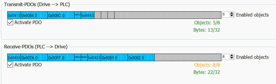
To comply with the various CiA 402 operating modes, a specific set of PDO must be mapped. For KEB, the standard mapping is as follows:
- – Transmit (Drive to PLC): Status Word, Position Actual Value, Velocity Actual Value, Mode of Operation Display, and Velocity Mode Actual Velocity Value
- – Receive (PLC to Drive): Control Word, Target Position, Target Velocity, Mode of Operation, Homing Method, Velocity Mode Target Velocity, Profile Velocity, and End Velocity
These mappings can be customized if desired to build upon the standard mapping, pare down if only select operating modes are required, or could be built from the ground up for specialized control.
For values that must be read/written that do not fall under the PDO, the SDO is used. While the PDO is continuously being transmitted between the PLC and drive, the SDO can be considered a one-time read/write. An example use of an SDO would be if the fault bit within the status word becomes true, the PLC could do a one-time read of the drive’s exception state to get a more complete error description.
State Machine
The state machine is used to define the actual operating state of the drive and how to change between operating states. The state machine is broken up into four quadrants:
- 1. 24V control voltage applied, power supply to the drive can be supplied
- 2. Power to drive applied, no torque at motor
- 3. Power to drive applied, torque can be applied
- 4. Torque at motor
Within quadrants 1, 2, and 4 there are multiple operating states and as discussed above, it is not possible to jump over states, but instead the operation must follow logically from quadrant 1 to quadrant 4.
The state machine is largely controlled from the PLC using the control word and information is passed back from the drive using the status word. Each is a 16 bit parameter and has a defined structure within the CiA 402 profile. Some of these bit’s effects change with the selected operating mode and some bits are left open to allow for customization by the device manufacturer.
Operating Modes
Finally, within the CiA 402 are a defined set of operating modes for motion control. These modes require the same commands from the PLC, have the same responses from the drive, and have the same operation to ensure interoperability between manufacturers. It is important to note that a vendor can state they comply with parts of the standard, but not the entire specification so it is important to verify a vendor’s product meets the functionality requirement.
KEB supports the following operation modes: profile position mode, homing mode, velocity mode, cyclic synchronous position mode, cyclic synchronous velocity mode, and cyclic synchronous torque mode. The mode can also be simply changed using the Mode of Operation RPDO. The variety of operating modes and ease of use ensures the CiA 402 drive profile with KEB drives can meet all motion control needs.
Related Story
KEB America Opens Sales Office in Canada
KEB America, Inc., a subsidiary of KEB Automation KG and the North American provider of motion control and industrial automation solutions, has announced the opening of KEB Canada at 2010 Winston Park Dr., Suite 200, Oakville, ON L6H 5R7. The Greater Toronto Area (GTA) sales office reflects KEB America’s growth and commitment to better serving North American customers in the Canadian market.