When and How Should I Select a Braking Resistor?
August 4, 2020
By Mike Keefe
When designing a motor control system, it is not always clear if a braking resistor is required and, if it is, how to proceed in selecting a braking resistor. This post is intended to simplify that process so it is clear when and how to select a braking resistor for your application.
Why are braking resistors necessary?
Braking resistors are introduced into a motor control system in order to prevent hardware damage and/or nuisance faults in a VFD. They are required because in certain operations, the motor controlled by the VFD is acting as a generator and power is flowing back towards the VFD, rather than towards the motor. A motor will act as a generator whenever there is an overhauling load (e.g. maintaining a steady speed as gravitational forces try to accelerate an elevator as it moves down) or the drive is being used to decelerate the motor. This causes the drive’s DC bus voltage to rise and will lead to over voltage faults in the drive if the generated energy is not dissipated.

There are a few basic ways to deal with the energy generated by a motor. First, the drive itself will have the capacitance to absorb some amount of this energy for a small amount of time. This is typically the case when overhauling loads are not present and a fast deceleration is not required. If there are portions of the duty cycle where the energy generated is too great for the drive alone, then a braking resistor can be introduced. The braking resistor will dissipate the excess energy by converting it to heat across a resistor element. Finally, if the regenerated energy from the motor is continuous or the duty is high, then it may be more beneficial to use a regen unit rather than a braking resistor. This will still protect the VFD from hardware damage and nuisance faults, but allows the user to capture and reuse the electrical energy rather than dissipating it as heat.
What should be considered when selecting a braking resistor?
Once it has been decided a braking resistor is needed for the application, there are two main factors when selecting the resistor: the resistance value and the power dissipation capacity of the resistor.
Minimum Resistance Value
 VFDs that use a brake resistor will also have a “chopper circuit” or brake transistor. When the DC bus voltage gets too high, the brake transistor shunts current from the DC bus across the brake resistor. This brake transistor circuitry has current limitations and the VFD manufacturer will typically list a maximum current value and duty cycle.
Since V=IR, if the voltage is constant then a smaller resistance will lead to a larger current. Thus if the max voltage is known to be the KEB over voltage level of 840VDC, it is possible to calculate the minimum resistance that would keep the current value below the braking transistor’s max current rating. While the minimum resistance value doesn’t affect the operation of the resistor or its ability to dissipate power, it is crucial to ensure it works properly with the VFD.

Power Dissipation Capacity
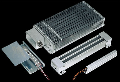
The second consideration when selecting a braking resistor is its ability to dissipate power. KEB braking resistors are listed with the amount of power they can safely dissipate if used continuously (PD) as well as three values for intermittent duty. Each of the numbers in P6, P25, and P40 refer to the cumulative number of seconds the resistor is used over the course of two minutes. For example, the KEB 10BR100-1683 resistor could safely dissipate up to 2200W for one stretch of six seconds over the course of two minutes or instead could do two cycles of three seconds each over the course of two minutes. 
Now that it is known what resistance values will safely work with the VFD and the power dissipation capabilities of the various resistors, it must be considered how much energy will be generated back towards the drive that will need to be dissipated. This will ensure the selected braking resistor has enough capacity to safely dissipate the energy generated from the motor. The first way to do this is through calculation. It is possible to calculate the power generated from the motor if the mass moment of inertia of the motor and load, motor torque, speed change, and time of the deceleration are all known. More information on performing these calculations can be found in the braking resistor manual. However, in real world applications it can be difficult to know and/or calculate the mass moments of inertia, particularly of the load. Because of that, it is commonly necessary to determine the proper power size of the braking resistor through a testing method. 
The general rule is that the larger the load and the faster the deceleration, the more power that will need to be dissipated. However, by utilizing the scope function in the Combivis 6 software, it is possible to record the drive’s DC bus voltage throughout the operation to get a more accurate picture of the braking resistor usage. With the scope it is possible to monitor if a resistor with greater power dissipation is required or if instead the resistor is sufficiently sized. In the latter scenario, it may be possible to adjust the operation to improve performance, such as making the deceleration faster.

Braking Resistor Installation
The final consideration when selecting a braking resistor is to ensure that it is installed properly. If a braking resistor is not installed according to UL standards, the circuit can fail in a manner that is a fire hazard. More information on safe connection of a braking resistor can be found here.
In addition to our traditional resistors, KEB is increasingly selling intrinsically safe brake resistors which fail much like a fuse protecting the system in the case of short circuit failure.
The installation environment is also important. Hazardous locations and installations with fibers (textile, sawdust) that are flammable will need special consideration.
Interested in learning more about how KEB drives and braking resistors can be utilized in your application? Contact an Applications Engineer at KEB America today!