A Guide to Communication Protocols for Absolute Encoders
April 5, 2021
By Jason Kelly, Electromechanical Design Engineer, CUI Devices
Automation continues to revolutionize the modern world. It goes beyond industrial automation and Industry 4.0 to include the commercial and consumer domains. This is where the wider IoT plays by automating tasks that were once physical but are now increasingly electromechanical.
In very general terms, electric motors provide a way of controlling the physical world. However, the majority of electric motors are relatively basic, meaning that they do not typically provide any feedback on their position. This is particularly true for low-cost motors used to simply move a load. It may be surprising to realize, but this can include relatively sophisticated applications, such as car seats that automatically adjust their position based on the key being used to open and start the vehicle.
The way these basic motors are given the necessary ‘smarts’ to know where the seat is and how to adjust it is through encoders. While some motors include encoders, those that do not can make use of external encoders designed to be fitted to the exterior of the motor shaft. There are various types of encoders used in these applications, each with its own way of detecting motion. This may include optical encoders that count light pulses as an object passes in front of a light source, or counting the pulses generated by a Hall effect switch as a magnet passes across it.
Some encoders, like the AMT Series of absolute encoders from CUI Devices, combine the high resolution offered by an optical encoder with the robustness of a magnetic encoder. They do this through capacitive encoding, which uses two plates: a transmitter and a receiver, separated by a third plate attached to the rotor. As the central plate rotates, it interferes with a signal being capacitively conducted between the transmitter and receiver. As the interference is not dependent on motion, the absolute position of the rotor plate can be detected even when it is not moving.
Common applications require the encoder to detect the speed of the motor or interpret the position of whatever the motor is moving based on the number of rotations. It may also need to detect the direction of travel. The way in which the position is reported can also vary. As mentioned above, an absolute rotary encoder is not dependent on knowing the previous position, as it provides a unique value for every quantifiable position of the rotor. This can be useful in applications that need to know the position of the motor after a power cycle, such as when someone gets into a vehicle.
Protocols used in rotary encoders
Whatever method is used to capture the physical motion, the information then needs to be passed to a controller. This is achieved by another level of encoding, which takes the raw pulses and translates them into a protocol for transmission.
The physical connection influences the choice of protocol and how it operates. In general, the protocol will either be synchronous, meaning it uses a clock signal, or asynchronous (no clock signal). In addition, the physical connection can be single-ended, or, to provide extra robustness, differential. This combination results in four possible alternatives and the most popular protocols covering these are the Serial Peripheral Interface, or SPI (single-ended, synchronous), RS-485, also known as TIA/EIA-485 (differential, asynchronous), and the Synchronous Serial Interface, or SSI (differential, synchronous).
Protocols are chosen for many reasons. They provide a level of interoperability, for one thing, but they also increase the robustness of the communication channel, particularly in electrically noisy applications, such as industrial motor control. But this does raise the question of what protocol is best for a given application. Fortunately, the AMT Series includes models that provide all three of the protocols mentioned above. Therefore, it is useful to look at each a little closer to fully understand their relative attributes in order to assist in the selection process.
The SPI Bus
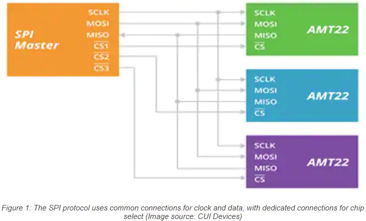
As a synchronous bus, one of the connections on an SPI bus is a dedicated clock signal (SCLK). The protocol also supports full-duplex operation thanks to dedicated connections for the Master device and the Slave device. As all data exchanges are coordinated by the clock signal, Master and Slaves can communicate without having to first negotiate parameters such as data rate or message length. Each Slave will feature a Chip Select pin (Figure 1), which allows the Master to control which device it communicates with at any given time.
As an example, the AMT22 Series features an SPI encoder that can be configured to operate with a 2 MHz clock signal. This means that when a Master requests it, the encoder can respond with its current position in as little as 1500 ns. The wiring configuration for the SPI protocol is also simple with dedicated connections for Master Out, Slave In (MOSI), and Master In, Slave Out (MISO) on each device. Each of these connections are wired together, as shown in Figure 1, while the Master has dedicated connections for the individual chip select pins.
As a single-ended bus, the SPI protocol is well suited to connections over relatively short distances of around 1 meter or less if using the high-speed clock. This distance can be extended if the clock speed is reduced, to preserve signal integrity. This makes the SPI protocol extremely versatile and suitable in several applications.
The RS-485 Bus
If the application involves distances greater than 1 meter, or if the environment presents a significant amount of electrical noise, a differential bus may be a better option. This is because a differential signal is inherently more robust than a single-ended signal. Another technique that can increase robustness is to remove the need for a clean clock signal on the bus. This is where the RS-485 bus and associated protocol can be an appropriate choice.
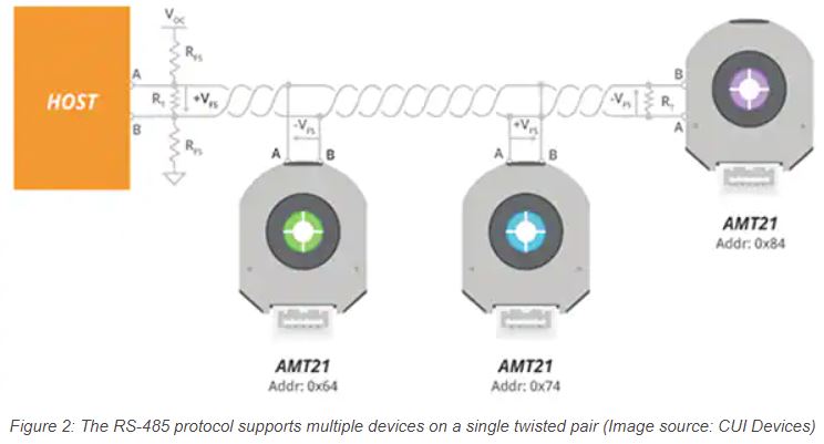
The RS-485 interface uses twisted pair cabling and, as it is differential, it needs proper terminations at each end of the cable. But because it is asynchronous, there is no dedicated clock signal on the bus, so it only needs two conductors (Figure 2), and it can reach data rates of 10 Mbit/s or even higher. As a bus, it supports multiple connections, but each must be terminated and impedance-matched to the cable. To maintain performance, each device should be connected to the bus using the shortest possible cable length.
The AMT21 Series uses the RS-485 bus/protocol, requiring just two connections for the twisted pair and two more for power. As it is asynchronous, all devices need to be aware of the way the protocol is configured and, by default, the AMT21 Series uses 8N1, which means 8 data bits, no parity, and 1 stop bit. In this configuration, the six most significant bits are used as an address, meaning one connection can support up to 64 individually addressable devices. The two least significant bits are used for the instruction. When instructed to provide position data, the AMT21 Series can respond within three microseconds. There are also instructions to reset the encoder and set the zero position.
The SSI Bus
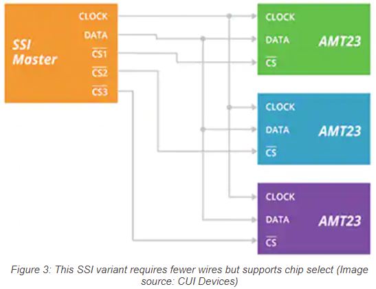
In its standard configuration, the SSI bus can be seen as an extension of the RS-485 bus through the addition of a differential pair that carries a clock signal alongside a differential pair for data. This means the standard SSI interface uses two differential pairs, or four connections, for clock and data. CUI Devices has developed a variation on this design, by removing the differential aspect but adding a chip-select pin. This reduces the pin count from four to three per connection while adding the convenience of a dedicated chip-select (Figure 3).
This variant is compatible with SSI controllers that support chip select and delivers performance levels that are similar to SPI. The AMT23 Series from CUI Devices uses this SSI variant and can be configured as shown in Figure 3.
Conclusion
The use of automation is only increasing. Absolute encoders, designed to be fitted to electric motors, provide greater control in automation applications. The capacitive encoding technology developed by CUI Devices and available in the AMT Series makes use of three communication protocols, each of which has its own features and benefits. This gives engineers greater design freedom when selecting the best technology for their application.